Now the fun starts, isolating a fault in a DC/AC feedback amplifier.
Blow any new transistors yet?
Now that you have one side working, it can be easier.
Hint #1: Use the ohmmeter and start comparing one pcb to the other, out of ckt. Nodal comparison method.
Are the driver transistors good on the ch that does not work?
I see that you did not buy the ksc1845/ksa???? pairs?
Good Luck
Rick
That's great that you have one channel working... its quite an achievment really.
So the second channels going to be the interesting one 🙂
D11 and D12 removed. We don't remove R1, we short it out to kill any possible input to the amplifier.
You must initially have the wire link in place shorting out Q11 and D6.
You fit ONE pair of outputs and with the bulb tester in place see what happens.
Make sure the "good" channel has no speakers connected if you leave that channel connected up.
A good thing is you have a fully working channel to compare to, which will help you narrow down the fault.
Its also possible that the good channel is drawing enough current (which is normal, nothing wrong) that the second channel tips the bulb over the point at which the filament resistance suddenly increases and so the bulb lights.
If you leave the good channel connected I would suggest you re apply the short across Q11 and D6 to force the current as low as possible.
Don't rush and make a note of everything you do.
If you leave the good channel connected I would suggest you re apply the short across Q11 and D6 to force the current as low as possible.
Don't rush and make a note of everything you do.
Lets hope so Jaycee. This could be a problem with the drivers but hopefully careful measurement and testing will reveal the culprit.
That's great that you have one channel working... its quite an achievment really.
So the second channels going to be the interesting one 🙂
D11 and D12 removed. We don't remove R1, we short it out to kill any possible input to the amplifier.
You must initially have the wire link in place shorting out Q11 and D6.
You fit ONE pair of outputs and with the bulb tester in place see what happens.
Make sure the "good" channel has no speakers connected if you leave that channel connected up.
I removed the working channel and then I tested the other one alone. All things are as you said, only one pair in, short Q11 and D6 and R1.
If I turn on the power the bulb light on and stay like that
Now the fun starts, isolating a fault in a DC/AC feedback amplifier.
Blow any new transistors yet?
Now that you have one side working, it can be easier.
Hint #1: Use the ohmmeter and start comparing one pcb to the other, out of ckt. Nodal comparison method.
Are the driver transistors good on the ch that does not work?
I see that you did not buy the ksc1845/ksa???? pairs?
Good Luck
Rick
Luckily enought I didn't blow anything. I will switch the driver transistors with the working channel so I can be sure they work. I probably miss the 1845, let's hope they will not be necessary
Remove these two resistors and then see if the bulb is out.
The bulb stayed on 🙁
Good 🙂
Refit those two resistors.
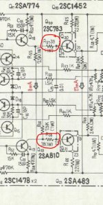
If you remove Q20 and Q21 from the PCB (the drivers) then the bulb should be off. Do that as a check.
What transistors did you order in the end as replacements for the drivers ? We can use MJE340 and 350 as a temporary measure for now.
I'll be back in a little while but don't rush ahead.
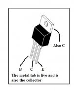
If the bulb is off when the drivers are removed then the next step is to replace both. An MJE340 for Q20 and an MJE350 for Q21 (unless you have something different). The pinouts for the MJE350 are the same as the MJE340.
Refit those two resistors.
If you remove Q20 and Q21 from the PCB (the drivers) then the bulb should be off. Do that as a check.
What transistors did you order in the end as replacements for the drivers ? We can use MJE340 and 350 as a temporary measure for now.
I'll be back in a little while but don't rush ahead.
If the bulb is off when the drivers are removed then the next step is to replace both. An MJE340 for Q20 and an MJE350 for Q21 (unless you have something different). The pinouts for the MJE350 are the same as the MJE340.
Good 🙂
Refit those two resistors.
If you remove Q20 and Q21 from the PCB (the drivers) then the bulb should be off. Do that as a check.
What transistors did you order in the end as replacements for the drivers ? We can use MJE340 and 350 as a temporary measure for now.
I'll be back in a little while but don't rush ahead.
If the bulb is off when the drivers are removed then the next step is to replace both. An MJE340 for Q20 and an MJE350 for Q21 (unless you have something different). The pinouts for the MJE350 are the same as the MJE340.
Without the drivers the bulb stayed off 🙂
I have:
four MJE340
six MJE350
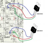
two MJE15032G
two MJE15033G
I made a stupid mistake, I inverted the driver transistors 
Now the bulb stay low but voltage on R1 is -9mv, no matter how I regulate VR1-2 it's alway negative, also between pin 9 and 13 there is no voltage
Only two o/p transistors (in the right position eheheh), Q11 D6 and R1 shorted, no D11-12, all the rest in
Now the bulb stay low but voltage on R1 is -9mv, no matter how I regulate VR1-2 it's alway negative, also between pin 9 and 13 there is no voltage
Only two o/p transistors (in the right position eheheh), Q11 D6 and R1 shorted, no D11-12, all the rest in
I'm going to be out of time for today so don't rush and don't run on ahead 🙂
With the transistors correctly fitted it should hopefully adjust correctly with VR1.
Remember VR2 will do nothing because we have its circuitry shorted out.
If it doesn't work then, detail where you are up to and what is happening and wait 'till tomorrow 🙂
With the transistors correctly fitted it should hopefully adjust correctly with VR1.
Remember VR2 will do nothing because we have its circuitry shorted out.
If it doesn't work then, detail where you are up to and what is happening and wait 'till tomorrow 🙂
I fitted the two transistors as showed, now voltage at R1 is correct (oscillate between positive and negative) but there is still no voltage between pin 9 and 13
Anyway to make this thread a sticky? Just watching the process of systematically debugging and repairing a dead amp has been very educational for me, and others too I suspect. Maybe not a sticky, but beginners like myself should read this stuff.
Thanks to Mooly for taking such a detailed interest in helping gde3 on this, and letting the rest of us see the process in detail.
Thanks to Mooly for taking such a detailed interest in helping gde3 on this, and letting the rest of us see the process in detail.
I fitted the two transistors as showed, now voltage at R1 is correct (oscillate between positive and negative) but there is still no voltage between pin 9 and 13
You mean L1, not R1, the output. So the voltage can now be trimmed to 0.00 That's good.
You wont have voltage between pins 9 and 13 yet because of the short across the Vbe multiplier Q11.
So, next step is to set VR2 to minimum resistance (as before) and then remove the shorting link and retest. You should then have the voltage between pins 9 and 13 and it should adjust with VR2.
(thanks for the kind words Dan. Fault finding has to be methodical)
L1 is -5mv, I removed the short on Q11 but voltage at 9-13 is still 0.
Voltage at Q11 collector is 1.6V, on the emitter -0.9V
- Status
- Not open for further replies.
- Home
- Amplifiers
- Solid State
- Help repairing Pioneer M3