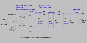
PS caps are 0.68mF 600V, 10uF 600V and 50uF 1k
Cathode cap is 30uF 100V
Cap to reduce B+ for the driver is 30uF 600V
330K resistor is 5W
Cathode cap is 30uF 100V
Cap to reduce B+ for the driver is 30uF 600V
330K resistor is 5W
Well you have a dead short somewhere. No wonder it’s popping.
astouffer: how could this be a dead short when the amp plays fine about 99% of the time, then a random loud pop occurs. Wouldn't the dead short prevent the amp from playing at all? Or, are you suggesting that the short occurs randomly (1% of the time) and thus, can be remedied by rechecking all solder connections?
... when the first cap in PSU penetrated.how could this be a dead short when the amp plays fine about 99% of the time, then a random loud pop occurs
It's a 600V cap, but initial peeks reached the 770V.
Maybe it's a self healing capacitor, the pierced part of foil is evaporated, then cap working again, but rectifier sooner or later died.
The second cap also undersized.
Attachments
Last edited:
euro21 - thank you for explaining that. much appreciated. Looks like I need to upgrade the 0.68uF and 10uF caps to 1kV. Very helpful!
euro21 - thank you for explaining that. much appreciated. Looks like I need to upgrade the 0.68uF and 10uF caps to 1kV. Very helpful!
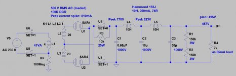
The bleeder resistors are also potentially undersized.
The most of the resistors limit voltage is only 600V, so two series 2-5W 150k resistor is better solution.
IMHO only one bleeder (across the last capacitor) is enough (the second choke DCR is eligible).
The bleeder resistors are also potentially undersized.
The most of the resistors limit voltage is only 600V, so two series 2-5W 150k resistor is better solution.
IMHO only one bleeder (across the last capacitor) is enough (the second choke DCR is eligible).
Is the 770V peak determined by the complete LCLC power supply or just the rectifier voltage?
The 770Vpk is related to the use of a capacitor before the first choke. Any use of a capacitor in that location is going to require a relatively high voltage part - with the voltage rating increasing for a lower capacitance. You appear to be using that first cap value as a means to achieve a certain B+ voltage that is part way between a typical choke input and a typical capacitor input style filter configuration.
In vintage choke input supplies, no capacitor was placed before the first choke, as it was just simpler to choose a rectifier with sufficient PIV and a choke with sufficient insulation voltage rating. That situation changes when ss diodes are used, as the rectifiers are faster and the voltage noise/glitches at the diode-choke node can get worse, and so a small cap to act as notch filter makes sense, even if it has to be higher than 1kVDC rating, and be rated for substantial ACV, as in your case.
You have also apparently chosen to use two 10H chokes, which introduces a level of oscillatory overshoot when compared to a simpler single choke filter, or at least making the second choke much smaller than the first. Typically this effect is not a concern for power supplies, but using a mercury vapour rectifier ends up applying a 'hot turn on' load to the power supply as all the load valves have their cathodes pre-heated (I assume). You can investigate this effect yourself using the simpler PSUD2 simulation software.
trobbins: thanks for helping. Great education for me and needed.
I chose the 0.68uF cap to increase the B+ to get 495V. That said, I am not obliged to use the 0.68uF cap and could go with the pure LCLC and get 424V, which would require a bias change, but otherwise would be happy to give it a try. Yes, I am preheating the 83 rectifier prior to B+.
Tomorrow the 1K caps arrive. More to come.
One other aspect you may or may not have appreciated is that your first inductor may not be operating with a continuous current waveform - a 50mA load is borderline. One issue is that Hammond don't provide the test ACV conditions for their 10H rating, or the ACV rating spec, and it may well be that the inductance is higher for the nominal 220Vac being applied across the choke (as well as a lower than rated DC current), and it's possible the choke may not be rated for that Vac level.
If the inductor current reaches zero then the winding may experience inductive voltage transients (when current starts/stops each half-cycle). If that was a concern, then using the two inductors in series would push operation more to continuous current operation, or alternatively adding some low input capacitance like 100nF may help.
If the inductor current reaches zero then the winding may experience inductive voltage transients (when current starts/stops each half-cycle). If that was a concern, then using the two inductors in series would push operation more to continuous current operation, or alternatively adding some low input capacitance like 100nF may help.
Here is the latest version that I plan to implement today. Notice the addition of the thermistors and diodes prior to the 83 rectifier. Also, will be replacing 0.68uF and 10uF caps with 1kV versions of the same. Let me know if you suggest other changes that might help with the random "pop" issue.
Attachments
The choke metal chassis have specific ground screw points that I have connected to the ground.
Khmmm....
The coil is at +600..700V potential -sometimes-, the core at ground.
Are you sure, that it is safe?
Update: the thermistors and diodes prior to the 83 rectifier have been installed. Amp has been playing for about 1 hour without any "pop" during the music. However, the "pop" still occurs when the B+ is powered on. Further thoughts? I read on Valvewizard that he recommends putting a 47k or 100k resistor across the hot & neutral of the B+ at the power switch. This supposedly prevents inrush current which causes the pop, according to Valvewizard. I would have thought the thermistors would have cured this, but it did not.
Euro21: I will have to ask Monolith Magnetics about the PS chokes.
Euro21: I will have to ask Monolith Magnetics about the PS chokes.
Can't find your standby switch in you schematic ??
IF the switch is after 1st cap (0.68uf) ... so this cap is charged during warm up.
Now you throw the switch, there is an inductor down the road, you will
have an inductive kickback across the switch.
Am I making sense ???
IF the switch is after 1st cap (0.68uf) ... so this cap is charged during warm up.
Now you throw the switch, there is an inductor down the road, you will
have an inductive kickback across the switch.
Am I making sense ???
If no "standby" switch (which closed only after preheating) between secondary CT and first capacitor "ground", the MV rectifier will go to the evil again.
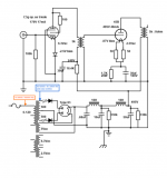
There are 2 switches as follows:
Switch 1: Passes mains 125V AC to the power transformer. The power transformer passes AC voltage to the heaters for all the tubes.
Switch 2: Passes power transformer 500/500 Vac to the power supply circuit before the solid state diodes. This is before the 83 rectifier and LCLC circuit.
"pop" occurs when Switch 2 is turned on.
See attached schematic. Not sure how to properly identify the switches, so I added some text to identify location of the switches.
Pat
Attachments
I would rather use 3 switches.
1.) the mains switch:
2.) MV rectifier safety switch in secondary HV coil CT wire (switched on when mercury evaporated);
3.) standby switch from rectifier tube cathode to PSU (switched after few seconds of 2.) switch).
If you paralleled it with -for example- 10k 25W resistor, the PSU capacitors p recharging is solvable.
CAUTION!
There are 600-700V potential on the switch and resistor!!!!
Attachments
- Home
- Amplifiers
- Tubes / Valves
- Help please: Bias and hum