I would have thought that practical tests with a small range of both resistive and speaker (or psuedo speaker) impedance loads would be a much simpler way to gauge achieved distortion and max power capability for a particular idle point. Then move the idle point in a direction that seems reasonable and repeat the tests. No guesswork then.
And taking DIY distortion measurements with stepped signal levels is such a breeze nowadays, especially comparing to the 1940-60's, and even up to a decade ago.
And taking DIY distortion measurements with stepped signal levels is such a breeze nowadays, especially comparing to the 1940-60's, and even up to a decade ago.
Indeed. This can be done with an external sound card, minor additional protection circuitry and a laptop (with appropriate software of course).
But I think for must DIY projects, just looking at the plate curves and some common sense will tell you where a good operating point should be.
If a recent, reputable manufacturer stopped measuring a plate curve at some point, it probably wasn't because of equipment limitations on their side...
Ian
But I think for must DIY projects, just looking at the plate curves and some common sense will tell you where a good operating point should be.
If a recent, reputable manufacturer stopped measuring a plate curve at some point, it probably wasn't because of equipment limitations on their side...
Ian
Last edited:
Just saying - measurement will always beat a best guess, until experience with the actual device and circuit kicks in. Especially when operating locus moves away from straight line, and starts encroaching on cut-off and saturation regions.
Thanks for the input soulmerchant / trobbins. Very educational.
Why does lowering the B+ and moving the operating point make sense? Is it because we want the operating point in the middle of the load line between the -0 and -100 bias points and thus will give the amp more breathing space before saturation?
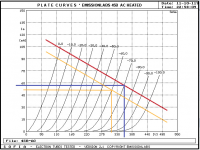
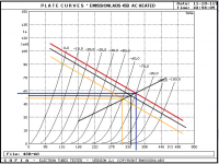
Please see attached load lines reflecting the proposed new operating point (orange lines). Roughly, this equates to 52mA and 305V. Question: once an operating point is selected, how important is it to dial in the exact voltage? Given our target is 305V, is 300 or 303 or 308 or 310 OK? Or is this done via ear/listening? Or measurement via an oscilloscope?
The 425V B+ assumes the 0.68uF c1 (in the power supply) is removed from the circuit. So, in order to get B+ lowered even further, I will need to insert a resistor after LCLC, correct?
Why does lowering the B+ and moving the operating point make sense? Is it because we want the operating point in the middle of the load line between the -0 and -100 bias points and thus will give the amp more breathing space before saturation?
Please see attached load lines reflecting the proposed new operating point (orange lines). Roughly, this equates to 52mA and 305V. Question: once an operating point is selected, how important is it to dial in the exact voltage? Given our target is 305V, is 300 or 303 or 308 or 310 OK? Or is this done via ear/listening? Or measurement via an oscilloscope?
The 425V B+ assumes the 0.68uF c1 (in the power supply) is removed from the circuit. So, in order to get B+ lowered even further, I will need to insert a resistor after LCLC, correct?
Attachments
Why does lowering the B+ and moving the operating point make sense?
How much did you pay for that tube, and how long would you like it to last? Why do you want to drive it to or past its max ratings? Are you just experimenting? Your PT isn't really suited for that tube if you don't want to waste its power with B+ dropping resistance.
Good website on load lines, etc.:
Drawing Load Lines
From Robinette's site:
"The operating point is the intersection of the plate load line and cathode load line. Notice how the bias point is just about in the middle of the load line from the 0 grid volt line to the bottom of the chart. That means this triode is close to being "center biased" which minimizes distortion and allows the maximum plate voltage swing before symmetric clipping begins.
A lower value cathode resistor will "warm the bias" by shifting the operating point to the left and up along the red load line. A higher value cathode resistor will "cool the bias" and shift the operating point down and to the right. Moving the operating point away from the mid point between the 0v grid line and bottom of the chart will reduce clean headroom"
This aligns with keeping the tube life longer, minimizing distortion and maximizing headroom. The attached load lines now identify the cathode load line (Black). Looks like the orange load line and operating points are a good balance of warm/cool bias, aka middle bias point.
Attachments
I'd use a rectifier like 5R4 for voltage drop before using a resistor. Let the heat escape from above. It has a low filament current, too.
If you ballpark 50mA idle, and the Vak=400V examples on the Emissions Labs webpage, then Vak would swing from circa 150 to 650V. How well that keeps away from saturation and cutoff, including for inductive loadline, is perhaps best checked by measurement.
good idea, 20to20.
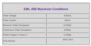
Pat, forget anything I've posted for this. That table of suggested operating voltages is confusing because it says Vb and Ua are different by Ug (-87v). That means Vb is the plate voltage, and I have no idea what Ua is if it isn't anode voltage. So carry on and good luck getting this set up for reliable operation. Not to mention reading somewhere that the 45B has a 420v max plate voltage.
Last edited:
OK, EML says 420v max plate.
And that prior posted table is for SE cathode biasing and Vb is supply B+ not plate voltage and Ua is plate voltage.
And that prior posted table is for SE cathode biasing and Vb is supply B+ not plate voltage and Ua is plate voltage.
Attachments
Last edited:
I reckon Ua is actually Uak, by inspection of the Emission Labs webpage:
Emission Labs. Information about life time of electron tubes.
Emission Labs. Information about life time of electron tubes.
Update and questions:
One of the two monoblocks is up and running nicely. Yea! Here are the measurements:
changes since last schematic:
274B rectifier is being used
C3g is wired in Triode mode
c1 0.68uF cap was removed
B+ : 424V measured from 274B pin out prior to LCLC
B+ : 418V after C2 in LCLC
C3g LED bias : -2.1V
C3g Anode : 164V
45B bias: -66V
45B Anode: 405V
45B : 55mA
hum: 2mV
I have yet to be able to clip the amp. No clipping with volume control from passive pre-amp turned all the way up. So, my question is: can we get more power out of the amp? My gut tells me yes. So, how do we do this?
1. Higher voltage on the C3g Anode? I see many people running C3g at 200V. Max spec is 220V
2. Change bias of C3g?
3. Run C3g in Pentode mode which, I believe, would have higher amplification factor.
4. Increase B+ of 45B?
Thoughts?
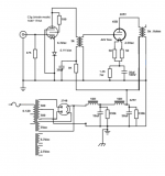
Here is the latest schematic
One of the two monoblocks is up and running nicely. Yea! Here are the measurements:
changes since last schematic:
274B rectifier is being used
C3g is wired in Triode mode
c1 0.68uF cap was removed
B+ : 424V measured from 274B pin out prior to LCLC
B+ : 418V after C2 in LCLC
C3g LED bias : -2.1V
C3g Anode : 164V
45B bias: -66V
45B Anode: 405V
45B : 55mA
hum: 2mV
I have yet to be able to clip the amp. No clipping with volume control from passive pre-amp turned all the way up. So, my question is: can we get more power out of the amp? My gut tells me yes. So, how do we do this?
1. Higher voltage on the C3g Anode? I see many people running C3g at 200V. Max spec is 220V
2. Change bias of C3g?
3. Run C3g in Pentode mode which, I believe, would have higher amplification factor.
4. Increase B+ of 45B?
Thoughts?
Here is the latest schematic
Attachments
If you ballpark 50mA idle, and the Vak=400V examples on the Emissions Labs webpage, then Vak would swing from circa 150 to 650V. How well that keeps away from saturation and cutoff, including for inductive loadline, is perhaps best checked by measurement.
A+
OK, EML says 420v max plate.
And that prior posted table is for SE cathode biasing and Vb is supply B+ not plate voltage and Ua is plate voltage.
yup.
Update and questions:
One of the two monoblocks is up and running nicely. Yea! Here are the measurements:
changes since last schematic:
274B rectifier is being used
C3g is wired in Triode mode
c1 0.68uF cap was removed
B+ : 424V measured from 274B pin out prior to LCLC
B+ : 418V after C2 in LCLC
C3g LED bias : -2.1V
C3g Anode : 164V
45B bias: -66V
45B Anode: 405V
45B : 55mA
hum: 2mV
I have yet to be able to clip the amp. No clipping with volume control from passive pre-amp turned all the way up. So, my question is: can we get more power out of the amp? My gut tells me yes. So, how do we do this?
1. Higher voltage on the C3g Anode? I see many people running C3g at 200V. Max spec is 220V
2. Change bias of C3g?
3. Run C3g in Pentode mode which, I believe, would have higher amplification factor.
4. Increase B+ of 45B?
Thoughts?
Here is the latest schematic
Start looking at the C3g triode specs sheet and plate curves. 🙂
Don't use C3g in pentode. Its a fantastic pentode, but its far better in triode (just my opinion though).
Questions: do you really need more power? what sort of speakers are you using? In what kind of room?
Ian
Ian, 90% of the time, I listen to classical chamber music. On my 90db speakers in a medium sized room, the output level is just fine. 10% of the time when I venture over to Zeppelin/Floyd/Rush, then I would like the extra headroom. But, not at the expense of tonality, purity, etc. The whole goal of these amps was to play violin/cello with lifelike tonality, harmonics and dynamics.
banpuku, perhaps better to add part designators to schematic if you are then going to refer to them in posts. Also the 45B cathode is +66V, so perhaps put "Vgk = -66V" on the schematic to avoid confusion. Same goes for first stage.
Measuring the voltage at the rectifier/choke node may be difficult for many meters as that node has both a high DC and AC voltage level. In reality any voltage measurement at that node (other than a scope waveform) has no practical use imho, and it is the first filter C voltage that is of more use.
You need to confirm the AC pk voltage swing generated at the input stage anode, and at the output stage grid, and relate that to the expected turns-ratio of the coupling Tx, to appreciate how close either stage is getting to cutoff/saturation levels.
Also the interstage transformer won't be presenting the first stage with a 5k loading, as you haven't loaded the output stage grid circuit, so at present your coupling transformer loadline is effectively horizontal. As such, you may get over 100Vpk swing before noticeable grid conduction/saturation effects start.
Need help on one amp misbehaving.
These are the symptoms:
1. The B+ to C3g plate RC network is not dropping voltage. I have tried multiple different resistors and capacitors, and no luck. 345V B+ is the same value before and after the RC network.
2. C3g bias LED is not lighting up. Measured voltage of C3g bias = 0V
3. 45B ammeter is measuring about 20mA, well below the target.
I tried switching tubes and that is not the issue, as both sets of tubes work well on the other monoblock.
Thoughts? Help!
Why is this happening? Ideas?
- Home
- Amplifiers
- Tubes / Valves
- Help please: Bias and hum