banpuku,
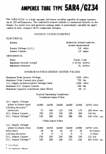
Your transformer high voltage secondary in your schematics is 500-0-500 Vrms.
The 5AR4 maximum rating for the high voltage secondary is 450-0-450 Vrms.
That is a major problem, not enough rectifier voltage rating.
You should use a pair of damper diodes.
You should use a separate 6.3V filament transformer to power the filaments.
For example, use a pair of 6BE3 single rectifier diodes.
They use a different socket.
Damper diodes are soft start, no more switches, no more relays, no more Pops!
banpuku,
Your transformer high voltage secondary in your schematics is 500-0-500 Vrms.
The 5AR4 maximum rating for the high voltage secondary is 450-0-450 Vrms.
Please see attached. For a choke input PS design (which I will achieve by removing the 0.68uF c1), the max is 550V. That said, I may consider the TV diodes like you stated. This will be a change that will take some time to achieve, but likely headed in that direction.
Pat
Attachments
When switch 2 is open,
won't the lower leg diode be conducting ???
IF that is the case, you have a half-wave regulated
PS running. 45B can sing at that point.
What is B+ when switch 2 is open ?
won't the lower leg diode be conducting ???
IF that is the case, you have a half-wave regulated
PS running. 45B can sing at that point.
What is B+ when switch 2 is open ?
Switch 2 controls both legs of the diode. The way it is setup is as follows:
1. Switch 1 sends mains AC to Power Transformer, which in turn sends AC to filaments. Also, this creates the 500/500 legs. BUT, both legs are only sent to switch 2 which is OFF at this point.
2. Switch 2 now has 500/500 legs, but is switched OFF. Once Switch 2 is turned ON, both legs of the 500/500 AC are sent to the rectifier.
Hope this makes sense.
If you included an ss diode in series with each plate of the 83, you could use just a single 'switch 2' that is in the HV CT link. In that location, the switch has one pole at ground level, although only 'switch 1' should be used to turn the whole amp off (as the switch 2 contact would have a hard time to open the circuit as it is effectively DC current). The ss diodes ensure that no reverse current flows.
You could have a 'switch 3' to short the speaker, so as to effectively mute the 'pop' caused by the OT primary DC current rise from zero to idle.
You could have a 'switch 3' to short the speaker, so as to effectively mute the 'pop' caused by the OT primary DC current rise from zero to idle.
Last edited:
I apologize, I didn't read the text in your schematic.
Take a look @ this blue bugle 45 amp:
Replies - Gerry E. - SET Asylum
similar to trobbins said.
Last resort: separate 2.5V filament transformer, ugly solution ??
Take a look @ this blue bugle 45 amp:
Replies - Gerry E. - SET Asylum
similar to trobbins said.
Last resort: separate 2.5V filament transformer, ugly solution ??
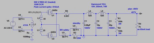
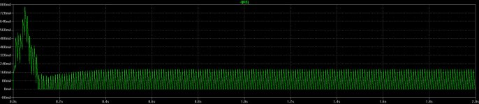
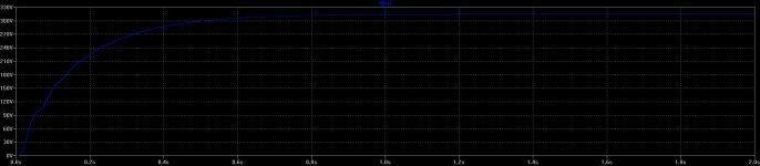
Without "Standby" the MV inrush current reaches almost 0.8A (pic 2).
(pic 1)
All switches OFF.
1.) Main switch ON: each tube heating. Mercury evaporating.
2.) When mercury evaporated, "MV safety" switch ON.
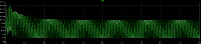
MV tube reduced current flow through R3 (pic 3).
B+ slowly rising to its reduced size (pic 4).
3.) 1-2 seconds later "Standby" switch ON, B+ is on full magnitude.
(pic 1)
All switches OFF.
1.) Main switch ON: each tube heating. Mercury evaporating.
2.) When mercury evaporated, "MV safety" switch ON.
MV tube reduced current flow through R3 (pic 3).
B+ slowly rising to its reduced size (pic 4).
3.) 1-2 seconds later "Standby" switch ON, B+ is on full magnitude.
Attachments
OK, team. Progress.
1. I have completely abandoned the 83 rectifier. Too much trouble with "pop" issues. I removed all the thermistor, sand diodes, etc that tried to cure the "pop" issue. In the end, the 83 was not made for this amp in my existing schema.
2. I have implemented both a GZ34 and 274B rectifier and also removed the 0.68uF c1. The amp turns on without any "pop". YEA! Thank you to those who helped along this journey!!! And to those who told me from the beginning to not use the 83, you were right!
Now, the GZ34 produces 425V (measured at the 45B plate). This is much less than my original plan of 495V, but that's OK. Now, I would like your input on the operating point. This is my first time choosing an operating point, so your input is needed.
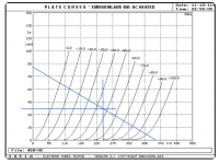
So, here is my first attempt at operating point selection. The 45B grid voltage curves & load lines are attached.
1. Load Line: from 425V (plate voltage) to 85mA (425/5000 = .0085). 5000 is the OPT primary impedance.
2. Operating Point Selected a point midway along the Load Line: roughly -45V (halfway between the -40 and -50 grid voltage curves). This operating point gives: 37.5mA, 240V
3. Cathode bias resistor: 45 / .00375 = 12,000 ohm resistor
Sound good? I want a good balance of highest output power and about 26-28db of 2nd harmonic distortion.
There isn't much data available (other than the EML website) regarding 45B operating points. EML does not show any operating points with a plate voltage of 425. So, this is virgin territory. You help is appreciated.
Pat
1. I have completely abandoned the 83 rectifier. Too much trouble with "pop" issues. I removed all the thermistor, sand diodes, etc that tried to cure the "pop" issue. In the end, the 83 was not made for this amp in my existing schema.
2. I have implemented both a GZ34 and 274B rectifier and also removed the 0.68uF c1. The amp turns on without any "pop". YEA! Thank you to those who helped along this journey!!! And to those who told me from the beginning to not use the 83, you were right!
Now, the GZ34 produces 425V (measured at the 45B plate). This is much less than my original plan of 495V, but that's OK. Now, I would like your input on the operating point. This is my first time choosing an operating point, so your input is needed.
So, here is my first attempt at operating point selection. The 45B grid voltage curves & load lines are attached.
1. Load Line: from 425V (plate voltage) to 85mA (425/5000 = .0085). 5000 is the OPT primary impedance.
2. Operating Point Selected a point midway along the Load Line: roughly -45V (halfway between the -40 and -50 grid voltage curves). This operating point gives: 37.5mA, 240V
3. Cathode bias resistor: 45 / .00375 = 12,000 ohm resistor
Sound good? I want a good balance of highest output power and about 26-28db of 2nd harmonic distortion.
There isn't much data available (other than the EML website) regarding 45B operating points. EML does not show any operating points with a plate voltage of 425. So, this is virgin territory. You help is appreciated.
Pat
Attachments
3. Cathode bias resistor: 45 / .00375 = 12,000 ohm resistor
Sound good? I /> Pat
.... check your decimal point position.
Yes: 45 / .0375 = 1,200 ohm resistor.
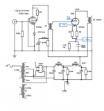
I put the 1,200 ohm cathode resistor in place. I am getting some odd measurements:
the ammeter measures 40mA (measurement location C, see attached)
45B grid vs. top of cathode resistor = -70V (measurement locations A & B, see attached)
hmmmmm. Thoughts?
I put the 1,200 ohm cathode resistor in place. I am getting some odd measurements:
the ammeter measures 40mA (measurement location C, see attached)
45B grid vs. top of cathode resistor = -70V (measurement locations A & B, see attached)
hmmmmm. Thoughts?
Attachments
Yes: 45 / .0375 = 1,200 ohm resistor.
I put the 1,200 ohm cathode resistor in place. I am getting some odd measurements:
the ammeter measures 40mA (measurement location C, see attached)
45B grid vs. top of cathode resistor = -70V (measurement locations A & B, see attached)
hmmmmm. Thoughts?
OK, at this point in your designing and testing you are working to establish the correct idle current and plate dissipation. NO SIGNAL. Disconnect the cathode cap and read the total resistance on the cathode to get the R value exact for your calculations. You may have some heater circuit weirdness and need to get it right. Pull the 45B to check the cathode R value. But your ammeter connections and operation could also be in question but just get the cathode R value accurate to start with so we can go forward. The calculated current is 58mA.
Last edited:
Just measured the cathode resistor without the 45B: 1.2K ohms
Ammeter is correctly connected, per Yamamoto instructions.
No signal. Signal input is shorted.
Double checked Anode voltage is 425V
Thoughts?
Ammeter is correctly connected, per Yamamoto instructions.
No signal. Signal input is shorted.
Double checked Anode voltage is 425V
Thoughts?
Just measured the cathode resistor without the 45B: 1.2K ohms
Ammeter is correctly connected, per Yamamoto instructions.
No signal. Signal input is shorted.
Double checked Anode voltage is 425V
Thoughts?
The 70v makes sense. You are running a high plate voltage. At 58mA. calculated, you have 355v A-K which is @ 20W plate dissipaton. That's close to the table values you posted earlier. Can't explain the ammeter reading of 40mA.
Figured out the ammeter. The ammeter requires a change to its own resistors any time the cathode resistors change. It now happily measures ~57mA.
So, how does do you get that 70V makes sense?
So, how does do you get that 70V makes sense?
Figured out the ammeter. The ammeter requires a change to its own resistors any time the cathode resistors change. It now happily measures ~57mA.
So, how does do you get that 70V makes sense?
Just general experience, and the table values you posted. With a high plate voltage, I wouldn't expect the bias voltage to drop from @90v to 45v with a cathode resistance change from 1.8K to 1.2K R.
banpuku, your loadline doesn't show a class A SE configuration. I suggest you translate the 5kohm loadline 'up' so that it intersects with the idle operating point at approx 370V and 50mA. Perhaps do some reference text reading on SE amps.
banpuku,
My Post #76 has an error. I got caught by the administrator 30 minute limit,
someone came to the door and distracted me.
The 5AR4 max voltage is too close to your B+ secondary voltage 500V versus 490V.
Your Pop! is the result of a warm 45 tube filament, and then B+ coming on suddenly when you switch the 83 B+ switch.
The 5Z3 is only rated for 450V transformer, not 490V transformer.
And the 5Z3 is almost instant on, because it is a directly heated filament (no cathode).
Find another tube rectifier, which meets the voltage rating of your transformer, and current draw of your amplifier.
They will have a little more voltage drop than the type 83.
Be sure to use a tube rectifier that is an automatic slow start, (indirectly heated cathode).
That way, you do not have to use a B+ [delay] switch.
No more Pop! at the amp turn on.
This problem can be solved with the right rectifier, you are not going to be able to solve it with the type 83 rectifier.
Damper Diodes.... need 6V heater, but hey.. wire two with the heaters in series and you can use a simple (cheap) 12V ballast transformer.
Maybe I suggested this in an earlier post?
I personally like the ugly coin-base late-60's early 70's ones of the RCA, Sylvania and GE variety... 6DM4A or 6DA4 are nice less obvious models I have gone for, and do not draw too much heater current either.
I have a BIG box full of them and am certain that I will die before I use them all. 🙂 If you pay more than 2-3 USD apiece for them, you are probably paying too much. 🙂 🙂 🙂
Ok, no pretty blue glow. instead, ugly red "swirly" heaters. Be prepared for them to last a long, long time.
They will outlast all your other valves/tubes... and are pretty hard to kill too..... such a really nice slow start-up. No POPs with turn-on either.
Last edited:
Figured out the ammeter. The ammeter requires a change to its own resistors any time the cathode resistors change. It now happily measures ~57mA.
So, how does do you get that 70V makes sense?
It is really worth learning ohm's law. If you are feeling lazy... bookmark this site:
Ohms Law Calculator
70V/1.2k=58mA
Purists might say 70V/1200 Ohms = 0.058 Amphere's
Ian
soulmerchant,
Thanks for putting up the purist number too, for those who are just starting.
They will now know the relationship of A to mA.
Velocity should usually be quoted in its most convenient units,
but there is another less familiar way:
Giga Furlongs per Femto Fortnight.
Powers of 10, combined with old units of length and time can describe things too.
banpuku, your loadline doesn't show a class A SE configuration. I suggest you translate the 5kohm loadline 'up' so that it intersects with the idle operating point at approx 370V and 50mA. Perhaps do some reference text reading on SE amps.
In another thread I kind of went over this for banpuku. Right now I think he is running these very nice and somewhat pricy 45B tubes a little on the hot side... just my opinion..
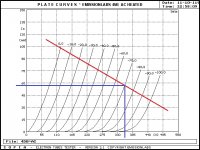
According to banpuku
A-K (Anode-Kathode) voltage = 425 - 70 = 355V
If you want to know why it is Anode-Kathode, remember that batteries are chemical elements, and in the late 19th through into the early 20th century the language of chemistry was very much a German domain...
From Ohm's law already, we know that the 45b is drawing 58mA
I took the liberty and drew a 5k "Load Line" on a screenshot of the plate curves (from the manufacturer's website) and moved it around until it overlapped with the point corresponding to that 355V and 58mA. This "Load Line" is not 100% true since our speaker is not a resistive device, but inductive. Nonetheless, it gives us a decent idea of power range the tube/valve will encounter.
Personally, I would be thinking of ways to get the A-K down to maybe 300V biased for 50mA. The plate would probably be at around 360V and the cathode (still using this 1.2K cathode resistor) should be around 60V for this to happen. Yes, this will mean less power, but there is a big benefit if it is done right. Basically I agree with trobbins. 🙂
This should still sound excellent, with great linearity, and allow for decent power and a bit longer tube/valve life.
I might have already mentioned it... but maybe not.. so let me add this:
I think the easy way to get the B+ down would be to remove that 0.68uF input cap in the power supply.
That would make the 1st choke work differently. It would immediately become an energy store, which from personal experience is one of the BEST reasons to build a tube/valve amplifier.
Choke input is a big benefit and really worth going for. 😉 It should be easy to try out. I don't see any downside to just removing that input cap and trying it out. Of course you can simulate it in PSU II before doing it first.
Ian
Attachments
Last edited:
- Home
- Amplifiers
- Tubes / Valves
- Help please: Bias and hum