Expected voltages,
Pin 1 +30 volts
Pin 2 no connection
Pin 3 0 volts
Pin 4 -30 volts
Pin 5 +30 volts
Pin 6 no connection
Pin 7 ground, so zero volts. Measure it though should 0.00
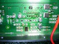
Pin 8 ???? I would imagine some negative voltage reading.... this is the mute pin. If it's zero 0.00 then this needs investigating. On your picture it looks to be tied in with those power transistors which makes sense... just see what it measures.
Pin 9 0.00
Pin 10 0.00
Pin 11 no connection
Pin 1 +30 volts
Pin 2 no connection
Pin 3 0 volts
Pin 4 -30 volts
Pin 5 +30 volts
Pin 6 no connection
Pin 7 ground, so zero volts. Measure it though should 0.00
Pin 8 ???? I would imagine some negative voltage reading.... this is the mute pin. If it's zero 0.00 then this needs investigating. On your picture it looks to be tied in with those power transistors which makes sense... just see what it measures.
Pin 9 0.00
Pin 10 0.00
Pin 11 no connection
Does the amp have a standby feature ? How do you turn it on.
What I am thinking is that those power transistors should switch the rails to the IC when the amp powers up... and also the logic level to those transistors will "unmute" the IC.
What I am thinking is that those power transistors should switch the rails to the IC when the amp powers up... and also the logic level to those transistors will "unmute" the IC.
No Standby, just an on and off switch on the front panel, I wondered if the mute feature might have kicked in on the previous chip during overload.
OK, bit of a puzzle that.
We need to alter the level on pin 8 to test. Hard to make out in piccy but does pin 8 go to a tiny surface mount resistor. There's a largish cap from pin 8 to ground... leave that... but can you isolate the resistor so pin 8 is "floating" with just the cap connected ?
We need to alter the level on pin 8 to test. Hard to make out in piccy but does pin 8 go to a tiny surface mount resistor. There's a largish cap from pin 8 to ground... leave that... but can you isolate the resistor so pin 8 is "floating" with just the cap connected ?
Start again on that... pin 8 is at the wrong level. The data sheet says muted if at zero volts or "open". Unmuted if -0.5 milliamp drawn from pin 8.
So with amp OFF do a check on ohms from pin 8 to ground... should NOT read 0.00.
Next with amp on, confirm pin 8 voltage again, then trace pin 8 and measure volts on both sides of that surface mount resistor that is appears to go too.
So with amp OFF do a check on ohms from pin 8 to ground... should NOT read 0.00.
Next with amp on, confirm pin 8 voltage again, then trace pin 8 and measure volts on both sides of that surface mount resistor that is appears to go too.
OK Mooly you are getting a bit technical, I will try to keep up. Pin 8 I think goes to a resistor then a transistor. The cap and resistor I think you are seeing actually goes over the top of 8 to pin 10. There is some flux between 8 & 10, tried to be neat, would this cause a problem?
Struggling with the piccy.
If you look at the data sheet you will see how pin 8 is normally connected in the typical application.
Pin 8 has a resistor that connects to the negative -30 rail, but it may be done via other circuitry... so where does that connection go ?
If you look at the data sheet you will see how pin 8 is normally connected in the typical application.
Pin 8 has a resistor that connects to the negative -30 rail, but it may be done via other circuitry... so where does that connection go ?
resistance red on pin 8 no reading, reverse leads rising resistance on 2000k setting, 1800 and still going up.
Voltage on 8 still zero on pin, on both sides resistor and top of transistor before it
Voltage on 8 still zero on pin, on both sides resistor and top of transistor before it
Sorry, I'll slow down. Flux won't cause a problem, iso or meths on a cotton bud removes it.
Pin 8 appears to have a problem in that it's being told to "mute".
If you have a really good camera a real cropped close up would help maybe.
The transistor will have to get it's control signal from somewhere... but as with any faultfinding we have to work back logically.
Pin 8 appears to have a problem in that it's being told to "mute".
If you have a really good camera a real cropped close up would help maybe.
The transistor will have to get it's control signal from somewhere... but as with any faultfinding we have to work back logically.
Resistance readings as expected OK
Need to establish why pin 8 appears muted. Those power transitors are the puzzle... why incorporate them if the amp has a single on/off switch. Does the amp "detect" audio at the input and then power up fully.
Mustn't overlook other obvious things too. The circuitry to the left in your piccy will probably run on lower voltage rails... are these present and correct.
What are the markings on that surface mounted IC as might be able to identify rails from that.
To my knowledge no detect audio, have been using a small radio with headphone output as a test signal. The chip says tl084c, there are two on the board another near the volume/phase/cutout controls.
mooly, dumb question but how do I detemine which is 4 & 11 just checked a few pins randomly and they are showing charge
Pin 1 is where the T is in TLO.
Pins 1 to 7 down that side, then back up the other to 14,
http://www.datasheetcatalog.org/datasheet/texasinstruments/tl084.pdf
Pins 1 to 7 down that side, then back up the other to 14,
http://www.datasheetcatalog.org/datasheet/texasinstruments/tl084.pdf
- Status
- Not open for further replies.
- Home
- Amplifiers
- Chip Amps
- Help noob fix sub amp