thanks Mooly. Here we go positive probe on B & C;
Working
B-A -0.62v
C-A -0.01v
Not Working
B-A -.02v
C-A -27.01 also makes a high pitched washy squeeling sound.
If I then connect B to C music returns and shows about 1.2 volts
Working
B-A -0.62v
C-A -0.01v
Not Working
B-A -.02v
C-A -27.01 also makes a high pitched washy squeeling sound.
If I then connect B to C music returns and shows about 1.2 volts
Those initial readings seem to show that the transistor is OK. The -0.62 volts indicates a PNP transistor. Collector at -0.01 volts show transistor fully on.
That's all correct.
Not working.
The base-emitter volts have disappeared and the collector volts have risen. So we have two choices here. It is possible for the small transistor to fail and give those results but they equally point to the transistor being "told" to turn off.
So we have to go further back into the circuitry to try and prove it.
Hard to tell from the picture. Does this look right ? If so the measure the voltages on this transistor working and not working. Put your negative meter lead on E and measure to B and to C.
Attachments
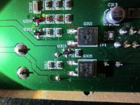
Trace looks right to me, the working numbers are;
B-E 0.52v
C-E 0.11v
On connecting B to E the music stops. Will post the non working figures - the amp sometimes works for quite a while before stopping.
B-E 0.52v
C-E 0.11v
On connecting B to E the music stops. Will post the non working figures - the amp sometimes works for quite a while before stopping.
If base is 0.52 volts positive with respect to emitter then Q304 is NPN. The readings are as expected for when it's working. Connecting B to E turns off the transistor and shuts down the negative rail.
A case of seeing what that base voltage does when faulty.
A case of seeing what that base voltage does when faulty.
Also, the amp was not failing, so I continued to run it whilst out of the house, the amp will now no longer work. In the past it was failing and I could measure and switch off. I suspect that if I replace the original diode again the amp will return to a "working" state. At present there is no (0.1v) on the rail we are investigating, the other rail continues to show +35.5v. 😕
Just a thought, could it be a rectifier problem, I noticed a buzzing in the area of the transformer, I did not want to introduce distractions, however have checked that 24v Ac is coming from the transformer, but as mentioned virtually no power on one rail....Now that it is not working no buzzing...
The B-E voltage falling to 0.12v is why the rail is disappearing. It's being turned off.
This is really difficult to diagnose without a circuit and just working from pictures without having the actual unit to work on.
As long as the unswitched rails are OK (that's the voltage across the large caps that goes into the FET's) then there isn't a problem with the rectifier. You should always have the -35 volts to the FET.
The buzzing is probably nothing. It could be because the circuit is unloaded or drawing an unbalanced current when the rail collapses.
If you connect E and C together in the picture above then the rail should appear.
As it stands now we need to see where point B goes. All the readings so far show that the base drive is being told to be turned off. Whether that's an electronic issue or something physical is hard to say.
If we cast back to post #9 point 2 and ground is now showing 0.1 v whilst point 1 continues to show 35v. So hence my thought on the rectifier as the FET is not seeing the - 35v. From what I can see point B heads off to an IC but I will take another piccy
If we cast back to post #9 point 2 and ground is now showing 0.1 v whilst point 1 continues to show 35v. So hence my thought on the rectifier as the FET is not seeing the - 35v. From what I can see point B heads off to an IC but I will take another piccy
Something is wrong there. That's why I mentioned above that you should always have -35 volts to the FET. It's the output from the FET that is switched.
Could there be two problems here and something has happened blowing one of the fuses or there is a physical problem such as a hairline crack in the print ?
The rectifier would be way down the list of suspects tbh. If they fail it's by going short circuit 99% of the time.
You need to measure the AC voltage from the transformer with respect to ground. I would expect around 25 volts AC on each of the two leads from the transformer. That voltage should appear at the respective leads of the bridge. If that is OK and there is still no -35 volts then it would point to the rectifier but I think the problem here will be physical or a fuse.
Whether there is another problem we will have to see.
- Status
- Not open for further replies.
- Home
- Amplifiers
- Chip Amps
- Help noob fix sub amp