Hi Guys,
Just seeking some direction, find the world of pcbs daunting but learning and reading as much as possible. Have a multimeter thats it.
The amp in question is a Jamo SW1008. The amp failed very shortly after I put very high voltage through the inputs via kx project - as I raced to turn it off it stopped of its own accord. Took it apart, driver fine tested elsewhere, checked what i think are the power transistors and mosfets acording to various methods (bcae the reference), current coming out of transformer 24v per side. No light from lamp led.
Replaced chip amp LM3886TF with LM3886T - led now comes on! 🙂 No sound though. Have bought replacment power transistors, will try putting these in next although as I say existing seemed to work ok. Am wondering would there likely be damaged caused to a protection circuit - or does all that happen inside the chip? Have i damaged something on the input side rather than the output? Sorry this is all so basic, but am out of my depth😱. Thanks for any guidence, will add information/pics if someone can tell me what is relevant
It's a circuit we need to see... piccys might help.
What did you connect to the inputs ? A DC voltage, an AC voltage, or just a very high level audio signal.
Fault finding at a basic level involves first checking all supplies are present and correct. Power transistors if they have failed usually go short circuit collector to emmiter.
Look at the data sheet for the LM3886, identify the supply pins and see if the voltage is present. Measure the voltage on the output pin next.
Data sheets available here for most semiconductors,
Datasheet catalog for integrated circuits, diodes, triacs, and other semiconductors, view
just type the device code in the blank box.
The LM3886TF is in a plastic case, the LM3886T has an exposed tab which (if I remember correctly) has the negative supply on it. So if the heatsink is grounded, you will cause a short unless you use an isolation like a mica insulator or a piece of silpad and plastic bolt washer.
Hi Mooly & Redshift thanks for you advice,
Will try to put a pick up tomorrow, it was a high level audio signal that caused the problem. Have checked the power transitors and seem ok, as mentioned have switched the LM3886T for the TF and yes redshift you are right, there is an exposed tab, which is grounded, the heatsink attaches to the external metal plate for additional cooling with multiple metal screws, would i have damaged the new chip - could short be the reason it doesn't work (dumb qn probably), could not get the TF and from reading the data sheet thought they were same 🙁
Will try to put a pick up tomorrow, it was a high level audio signal that caused the problem. Have checked the power transitors and seem ok, as mentioned have switched the LM3886T for the TF and yes redshift you are right, there is an exposed tab, which is grounded, the heatsink attaches to the external metal plate for additional cooling with multiple metal screws, would i have damaged the new chip - could short be the reason it doesn't work (dumb qn probably), could not get the TF and from reading the data sheet thought they were same 🙁
I don't know if you would have damaged the chips, it probably depends on whether the fuse blew or you turned it off fast enough. You would have to test them to find out.
When you next power up it's worth using a filament bulb in series with the mains supply to the amp of 60 watts or so. If anything draw excess current the bulb lights and it can save burn ups etc.
You need to be logical fault finding. I assume it runs of split supplies -/+ rather than single ended AC coupled... but it may not... without seeing circuit only you know. If it's DC coupled (split supply) the output must be at zero volts DC... is there a protection circuit/relay stopping the speaker connecting because of DC offset (fault) ?
You need to be logical fault finding. I assume it runs of split supplies -/+ rather than single ended AC coupled... but it may not... without seeing circuit only you know. If it's DC coupled (split supply) the output must be at zero volts DC... is there a protection circuit/relay stopping the speaker connecting because of DC offset (fault) ?
Thanks for your persistance guys, have attached a couple of photos that I hope will clarify. I tried to power up with the chip isolated from ground, the amp led came on briefly but then went out. Tried grounding again and light comes on and stays on. I also tried to get a schematic form Jamo, they said they didn't have one for this model?? Am hoping with the pictures you can give me a lead on what next. I also found a place that can supply a TF - but am wondering if this is the problem😕
Attachments
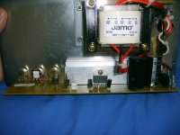
Also have taken some voltage measurements on the dc side of the regulator - shows 0.5V negative on the positive 35V (in the picture the lower circuit). Is this how it should be? 25V AC out of both sides of transformer.
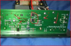
Can you measure the DC voltage at the four points shown and post the results. Make sure the chip doesn't get hot. Do not connect any speaker either.
The two devices ringed look like transistors used as "switches" to control the main power rails to the IC.
You may well find it's one of these and the IC that's the problem.
The two devices ringed look like transistors used as "switches" to control the main power rails to the IC.
You may well find it's one of these and the IC that's the problem.
Attachments
Hi Mooly,
Results are (am guessing I am measuring from each point to ground)
1. 35.2V
2. 0.5V
3. 35.2V
4. 0V (meter shows negative sign in front of this, reverse lead same result)
I did what I thought were the correct tests on these mosfets before(in circuit), I'm guessing a zero reading is not a good sign?
Also do you think the new IC that is not isolated will be a source of problems, ie because it is the T and not the TF?
You must be sure you are measuring from ground... keep the black meter lead on the main ground which in the above picture is the print above where I marked 1 and 2 for voltage readings. Sounds like you are though.
I can't make it out in the picture but right hand side are two surface mounted white components... are they fuses ? F301 and F302.
With it off measure both on low ohms range, should read 0.00. Is one open circuit ?
Your voltage readings indicate a rail missing. Points 1 and 3 appear OK at 32 volts. Points 2 and 4 should be negative 32 and that's missing.
I can't just see on the data sheet I have which pin is connected to the metal tab on the non-isolated version. It's often the most negative part of the "die" or substrate within an IC and not neceassarily the ground pin.
Without having an IC and your amp in front of me I can't say. Safest is to assume that it's isolated for a reason, so if you use a non isolated IC then fit mica washers. Some of the large transistor ones would cover the tab as ones specifically for the IC package never seem to be listed anywhere. If you use mica, also use a thermal grease. Mica is better than the cleaner flexible silicon washers... all depends what's available though.
Also another check... can you read on ohms (and diode check) between points 1 and 3 and 2 and 4 in the piccy to make sure those transistors are not short circuit. If short they will read 0.00 on ohms.
Edit...
Parts,
http://tinyurl.com/2uckxfr
http://tinyurl.com/334xhc3
Last edited:
Hi Mooly,
Here is the latest, am pretty sure of the voltages, am using the ground you mention which goes to the negative on the woofer.
Yes they are fuses I could have sworn I have checked these, the negative rail is giving funny readings, basically zero resistance on the good rail, showing 1700 ohms (on 2000k setting) on the "bad" rail, if I reverse the leads on "bad" rail/fuse shows open circuit.
On Diode check between 2 & 4 showing 600 (positive on 2)
On Diode check between 1 & 3 showing 628 (positive on 3)
Resistance between 1 & 3 16.8 (on 200 setting)
Resistance between 2 & 4 0 (on 200 setting)
Have not ordered any parts as yet, nor isolated the chip, but to summarise would it be fair to say that one of the fuses has tripped, so if I replace that and isolate the chip I could be back in business?
Hopefully that's all that's needed.
And it is worth using a bulb tester... having seen the PCB a 60 watt or so would work well.
Usual disclaimers apply 😉 with the proviso that it's rebuilt correctly in the end.
Use the bulb in the primary side... short out the blown fuse and test. Even if there were a dead short somewhere all that happens is the bulb lights.
Is there a chance the original IC is in fact OK and the fuse is the only problem ?
As the overload was just excessive signal rather than a short on the output there might be a good chance.
Fuses like that are expensive, and it's not worth keep blowing them so use the bulb until it's fixed.
If you do connect a speaker with the bulb in place use very low volume only as the rails will drop very quickly under load and may cause the IC to "latch" unpredicatably.
Always make sure there is zero DC volts at the speaker terminals before connecting speaker.
I think I am starting to go crazy  . This only just occurred to me now. The fuse I thought was faulty and giving funny readings is on the rail producing 35v! This is the fuse which has point 1 on it. OK so use logic - put the bulb in place of the fuse, still 35v, shorted the fuse, still 35v. Ok so it must be the "good" fuse which has point 2 on it. Put the bulb in 0.5V, short the fuse still 0.5V. Checked the AC output again to see if something is tricking me - still 24V each side!!!!!
What am I doing wrong, have I just been looking at this too long??
Incidentally isolated the chip with just a thin piece of plastic between the heatsink and the outside plate, checked the resistance between the metal tab on the chip and ground (shows open circuit). The original chip could be salvageable however I thought I could maybe do more damage to the pcb by removing and reinstalling?
. This only just occurred to me now. The fuse I thought was faulty and giving funny readings is on the rail producing 35v! This is the fuse which has point 1 on it. OK so use logic - put the bulb in place of the fuse, still 35v, shorted the fuse, still 35v. Ok so it must be the "good" fuse which has point 2 on it. Put the bulb in 0.5V, short the fuse still 0.5V. Checked the AC output again to see if something is tricking me - still 24V each side!!!!!What am I doing wrong, have I just been looking at this too long??
Incidentally isolated the chip with just a thin piece of plastic between the heatsink and the outside plate, checked the resistance between the metal tab on the chip and ground (shows open circuit). The original chip could be salvageable however I thought I could maybe do more damage to the pcb by removing and reinstalling?
Not sure if this is relevant but reading on both sides of top fuse (F301) is 24v AC and reading on the bottom (F302) is 24V Ac on the input or transformer side and approx 36.6 V AC on the output or rectifier side. Could the rectifier be the problem - don't really understand what this is or does...
OK I should not be left to my own devices-
Checked rectifier using diode test all seemed ok. Removed suspect fuse, replaced with inline bulb, did not light, turned on no joy - similar voltages as before. Next removed good fuse put where old fuse was - powered up to see what would happen - good news 35V plus and minus - strangely without the other fuse in (F301), quickly turned this of just in case. Now connect bulb to F301 position. Voltages now low like +5 and -5 nothing connected.
Now I think when i tried power up with just one fuse and no bulb i smelled burning, actually thought it was the single fuse.
So try 2 bulbs - result now is that the rail formerly on 35V is 13.4V and the other rail is about 0.6V. Using a 40W and 15W fridge bulb - I know but it's all flourescent bulbs in Australia now so have no higher wattages.
Also transformer still at 24V AC.
Help Mooly, help anyone, am determined to fix this thing.
P.S the plastic on the heatsink is just a temporary measure
The bulb goes in the mains side of the transformer 🙂 A 40 watt one should be OK as this amp draws little current under no signal conditions.
It connects in series with the primary of the transformer limiting the current.
If you smelled burning we go back to the start...
1. First fit the bulb as described. Don't switch on.
2. Measure across each fuse on ohms/diode check and confirm which is OK. If it reads 0.00 it's good. Anything else and it's no good... remember slight voltages remaining across caps etc cause havoc with "in circuit" resistance and semiconductor checks giving wrong/varying/erratic readings... but when we are looking to confirm that a fuse is OK then it's fine to test in circuit. So 0.00 is good... anything else no.
3. I assume a fuse is blown so short it out with a piece of wire temporarily... it's safe because the bulb in the primary limits current overall.
4. Is the IC fitted ?
If it is, switch on and see what the bulb does... it should light as the caps charge in the PSU and then go dim or virtually out. If it does measure the rails... they should be OK... and if the IC is good then the amp should work.
5. If the bulb stays lit brightly and the rails are low then switch off and remove the IC. Then switch on and check the rails again... if OK now then the IC is probably damaged.
Try that before we look any harder for a fault.
The rectifier should ! be OK... the above will prove it.
Edit... using plastic to insulate the IC may be OK just to get it working, but it's no good in use. The special washers, mica or silicon are designed to allow the heat to flow as well as possible through them... it's really important. Mica used with special grease or silicon washers fill the microscopic imperfections in the surfaces and allow good thermal conduction. A semiconductor can go from 20c to 100c in a second or two under load and if the heat isn't taken away it will fail.
Rectifiers... http://www.allaboutcircuits.com/vol_3/chpt_3/4.html
Last edited:
Light bulb tester,
http://www.diyaudio.com/forums/power-supplies/167579-light-bulb-tester.html
Again usual disclaimers and all,
solder wires to bulb, and connect bulb somewhere convenient so it's in series with the mains transformer. You can use an old mains plug with the fuse removed and the bulb connected in place of the fuse... or if there is a fuse in the amp, remove that and connect bulb across there. Do it safely and neatly and make sure you can't touch the bulb connections in use.
- Status
- Not open for further replies.
- Home
- Amplifiers
- Chip Amps
- Help noob fix sub amp