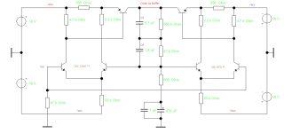
First of all, I would correct the time constants of the RIAA negative feedback network, which are quite misaligned.
The following deviations are present -6.145%, +1.634%, -2.153% in relation to the normalized three frequencies.
Sorry - but there are even more screws that have been tightened incorrectly. Of course, this only means that this phono EQ must sound fundamentally different from other representatives.
Without stepping on anyone's toes, because the PCB looks really nice, there's still room for basic improvement!
It actually sounds quite good. I haven't calculated your findings, and haven't got the knowledge yet to do so. But thanks for the feedback👍...
And yes, the unit does look good, witch makes proud. Initially I'm the only one looking at it every day, so why not get the pleasure from nice work😉
And yes, the unit does look good, witch makes proud. Initially I'm the only one looking at it every day, so why not get the pleasure from nice work😉

The deviations mean
in relation to the reference level at a frequency of 1kHz, the fundamental tone becomes more prominent; all in all, a relative band of +/(-) 0.61dB to -/(+) 0.18dB remains. In between lies the present dimensioning, mathematically.
This is actually still within the limits. The optimum ratio of C9 to C8 is 3.6... for R29 to R28 is 11.77... with 75µsec = R28 * C8 and 3183µsec = R29 * C9.
Perhaps the nice 5100pF and 1500pF cylinders were selected, measured in each case, so that in combination with the original carbon film resistors (tolerance +/- 5%) they are in the alignment of +/- 0.5dB.
Decisive resistors have already been exchanged and the two 36.5kOhm guys replaced with 500µA current sources / sink. If you change too much now, you might as well set up a new design with a slightly modified topology.
What else can you say? The fun factor and the joy must remain, on the one hand hard emperie and knowledge, on the other hand the famous snake oil. Both are perfectly fine.
Kind regards,
HBt.
Illustrating numbers, quick shotI did however match the 51.1k and 665kOhm as close to the schematic as possible when replaced with Dale-resistors.
C9 = 5.1nF
-> 624.137kOhm, 1.4166nF, 52.944kOhm
C8 = 1,5nF
-> 50kOhm, 5.4nF, 589.463kOhm
Is it a true story that Dan D'Agostino is the mastermind behind this phono EQ? I've liked the topology since the days of the Elektor SUPRA from 1982.
For the brave I'll add a quick thought,
the standard E12 series and the elimination of frequency compensation around Q6 & Q5 were leading thouhts.
How to approximate C9 and C8 remains an open question. But under no circumstances would I dismantle this beautiful EQ now.
For the brave I'll add a quick thought,
the standard E12 series and the elimination of frequency compensation around Q6 & Q5 were leading thouhts.
How to approximate C9 and C8 remains an open question. But under no circumstances would I dismantle this beautiful EQ now.
Attachments
@hbtaudio thanks a lot for the insight. I can't do this math, so very interesting indeed.
DIY is so much fun, but I'm always afraid of destroying the sound that made me solder the unit in the first place for further performance. It happens i go all in, but not always.
That said, I really like the sound form the Acurus RIAA, and thought that some small adjustments would raise performance, and keep the basic signature. And so it did.
I meassured the Vdrop across the 36.5kohm before pulling these to 468μA, and adjusted the CCS accordingly to 470μA. So quite safe investment with the CCS for now.
-But, looking at your calculations, the swap of four components would be interesting and easy to try, but I'm a bit confused how to read your suggestion:
(Quote)
"C9 = 5.1nF
-> 624.137kOhm, 1.4166nF, 52.944kOhm
C8 = 1,5nF
-> 50kOhm, 5.4nF, 589.463kOhm"
If I understand correctly, if C9 remains 5.1nF, then the following circuitry should be ~624kOhm, ~1.4nF and ~53kOhm. Correct?🙂
Thanks 👍
Last edited:
That's right,
I just wanted to illustrate the puzzle game.
Basically, there is nothing wrong with this product. What prompts us now to pick up the screwdriver and soldering iron? This question keeps me busy from time to time.
A defect (or a fundamental fault) is quickly repaired and explained, so it can't be that. In my eyes, two essential points remain. 1) I like the circuitry and the overall feel of the device. 2) I don't like the device or the product for reasons that aren't defined in more detail. In this case, I fiddle around with all sorts of things until I am reasonably satisfied. But often it is point 1, I am satisfied and perhaps even a little in love with the design (of the circuit). But now I have a fully developed product (with a certain number of units per year in production) without a superficial defect - what now?
In this case, I can't identify any defect or shortcoming. Yes, perhaps the well-known problem of the puzzle with the component values around the equalization network, but: should every manufactured device receive a special combination of suitable, measured components? Nobody can pay for that. As a manufacturer, I am therefore faced with a problem: I need a robust circuit and an acceptable alignment in order to survive and be able to produce at all.
I assume type 1 is getting to work. He wants to embellish his love a little more. What can he do if everything is actually in order? He can ensure better working conditions, slightly improve the power supply unit and replace various components with higher quality ones.
That's all you can and should do.
As a metalworker, you could of course think about various improvements to the housing or, as a designer, about the external appearance.
But there is very little potential for improvement on this device. The developer has done a great job. If you go too deep here, it is advisable to implement your own circuit.
Ultimately, it is a puzzle.
Thanks. I think most DIY'er have that itchy feeling, always wondering if even a perfect performing unit could be raised just a tad if. . . . . .............??? 🙂 I do.
-Alot of headache wondering in a good way of course, but also some good experiences that went way better then expected after some soldering. Other ideas scraped within the first 5sek of a listening session and back to the bench rewind the hole thing.
I'll try your calculations, just need to order some suitable values🙂
Best regards
I mean, I'm just a guy that needs to rely on others' expertise to work on my electronics, but there was a measured 12dB gain in signal to noise ratio vs what the Aragon 47K was rated at by the manufacturer (80dB vs 92dB after mods) with my unit.But there is very little potential for improvement on this device. The developer has done a great job. If you go too deep here, it is advisable to implement your own circuit.
That doesn't strike me as "very little" improvement. And that's just with specs, not sound (I think it sounds great, BTW).
But I'm not an engineer 🤐
In general I believe Acurus/Aragon are conservatively rated from factory, that doesn't mean the -92dB THD isn't true. Very important to notice!!
I don't read HBTAudio's comment as a negative statement. More like: mods can be performed, but it might be hard to achieve much beyond the well made factory topology.
-I just did my P10, and moving on form her could be somewhat tough without ditching the sonic signature of the unit itself, and going extreme..
The big advantage between the P10 and 47K is obviously the external PSU that comes with the 47K, but that doesn't necessarily mean that the 47K is much less sensitive to work on and mods might not work as promising at first or second take.
I did have to move the CCS in the P10 away from the input stage to shot it up, that's how sensitive these things are🙂
A danish forum actually advised that I should be very careful if the better PSRR from a CCS would be killed by adding unwanted noise to the circuit, and other people voted to leave the original 36.5kOhm in place for the same reason.
Best regards
Last edited:
Didn't mean to come across as negative 🙂
Plus, I am no engineer so I can get over my skis easily at this point re: audio/engineering
I can't attach the Word document with the specs on it unfortunately. There's a chance Kevin's custom-built LPS helped a lot too (original Aragon plastic one was DOA)
Link to the thread on AK: https://audiokarma.org/forums/index.php?threads/modialfan-aragon-47k-upgrade-magic.1022795/
Last edited:
I won't really recommend upgrading the internet PSU of the P10 as I did. New caps is fine, but adding a bigger transformer might cause problems with hum.
I think HBTAudio somewhere mentioned the possible benefit of further internal metal shielding, and this might actually be a great mod
I think HBTAudio somewhere mentioned the possible benefit of further internal metal shielding, and this might actually be a great mod
+12dB is huge, expressed as a ratio your SNR is now four times better than before the repair. In other words, the noise must only seem half as loud to you.That doesn't strike me as "very little" improvement. And that's just with specs, not sound (I think it sounds great, BTW).
In the first post I wrote that there is room for fundamental improvements. Should I therefore go into all the possibilities that can be exploited and justify them (because without factually correct justification, we are only moving in the realm of voodoo or snake oil)? I don't think that would be helpful.
I have seen the power supply circuit on the net somewhere. Well, that could actually be implemented "differently". But for what reason? The present equalizer is not bad and I don't want to hurt it, i.e. tweaking must be well thought out and sensible. You shouldn't go beyond a certain point.
Apart from a repair,
there is only one reason for a new, better power supply unit (PSU as an example), namely to have developed and built it completely yourself.
The phono pre has a certain requirement profile for its electrical supply, if this is fulfilled, more is a luxury - "better working conditions for our love".
😉
Perhaps you also have a personal prejudice against a certain implementation, which could also be a driving force.
Regards,
HBt.
@hbtaudio For a brief moment i thought it was "Ken Early Audio" speaking behind the username. He would write exactly in the same manner. Something like; "Keep things in perspective, why do it need overkill, when a more straight forward solution is right around the corner"
I've owned a build of his. The most musical preamp I've had to date, yet so simply build within specs. Respect
I've owned a build of his. The most musical preamp I've had to date, yet so simply build within specs. Respect
Hi. I just stumbled upon a 47k in my neighborhood here in Norway and I’m thinking about doing some mods like some of you have done.
A question.
A read somewhere that the IPS and Ingot power supplys are the same but with larger capacitors in the ingot.
10000mF I think it was.
Is that correc? Has anyone tried that?
A question.
A read somewhere that the IPS and Ingot power supplys are the same but with larger capacitors in the ingot.
10000mF I think it was.
Is that correc? Has anyone tried that?
A snapshot from the Aurum Ingot PSU🙂A read somewhere that the IPS and Ingot power supplys are the same but with larger capacitors in the ingot.
10000mF I think it was.
Is that correc? Has anyone tried that?
I included the full schematic of the Aragon Aurum to get the full picture off the PSU, including the CRC stage.
Attachments
Last edited:
- Home
- Source & Line
- Analogue Source
- Help me understand this circuit. Aragon 47k/Acurus P10 Phono Stage