Ok will short the ends...Okay. Always search the best point with the gang. And perpaps you can use the signal cap too to get more capacitance in the tuned circuit. For this, short both ends of the little gang.
It doesn't work with 27pF cap... grid voltage is -0,51v and no buzz on the radio.

My bad. Crystal fell out of its socket. I have -6.6v now with 27pf... should I continue and try with 22pf? Or even 10pf?Ok. Thus return to previous value. And reduce the anode load resistor (100K) to its half, 47K.
Plate is 102v now.
Should I reduce the anode resistor anyway?
I'm a bit lost with the gang... if I short both ends of the little gang (common and osc) I will short the gang, you ment the big end? Or maybee osc with big C?
Last edited:

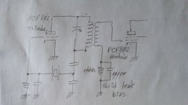
I had managed to get -7v by adjusting screw at the back of the gang...P: plate. R: decoupling resistor.
Shorting both extremes together makes oscillator to stop transmitting at about the center of it's travel and picks back up after the center, also voltage goes to -0.5v at the center...
With that said, should I still short extreme to plate and center to the psu?
Do you have at hand a short piece of thinner enamel wire; say .2 / .3mm diammeter and 30cm long?
I have 0.1mmDo you have at hand a short piece of thinner enamel wire; say .2 / .3mm diammeter and 30cm long?
Ok. With care, take the tank off the cicuit. Make two new holes in the plastic tube diametraly opposite with those you already have, the same way. Thus, with the new wire make a secondary winding introducing the new turns between the older ones, same # of turns.
o O o O o O o O o O
--------------------------------------
Inner of the coil.
--------------------------------------
o O o O o O o O o O
O : Gross wire
o: thinner wire
(Never I dreamed making ASCII ART here)
Thus we will have a single tuned RF transformer tightly coupled. Coupling is a measure of the percentage of the magnetic line forces inside the primary that can be tranfered to the secondary. Usually it is identified with the letter K.
0<K<1. This means K may be between 0 and 1. Close to zero is a light coupling, like your receiver to the transmitter antenna. Your K will be strong, close to 1.
But K never is zero nor one.
o O o O o O o O o O
--------------------------------------
Inner of the coil.
--------------------------------------
o O o O o O o O o O
O : Gross wire
o: thinner wire
(Never I dreamed making ASCII ART here)
Thus we will have a single tuned RF transformer tightly coupled. Coupling is a measure of the percentage of the magnetic line forces inside the primary that can be tranfered to the secondary. Usually it is identified with the letter K.
0<K<1. This means K may be between 0 and 1. Close to zero is a light coupling, like your receiver to the transmitter antenna. Your K will be strong, close to 1.
But K never is zero nor one.
Nicely explained.Ok. With care, take the tank off the cicuit. Make two new holes in the plastic tube diametraly opposite with those you already have, the same way. Thus, with the new wire make a secondary winding introducing the new turns between the older ones, same # of turns.
o O o O o O o O o O
--------------------------------------
Inner of the coil.
--------------------------------------
o O o O o O o O o O
O : Gross wire
o: thinner wire
(Never I dreamed making ASCII ART here)
Thus we will have a single tuned RF transformer tightly coupled. Coupling is a measure of the percentage of the magnetic line forces inside the primary that can be tranfered to the secondary. Usually it is identified with the letter K.
0<K<1. This means K may be between 0 and 1. Close to zero is a light coupling, like your receiver to the transmitter antenna. Your K will be strong, close to 1.
But K never is zero nor one.
Ok, will do it when I return. Now I have to visit my mother to change the doors in hers apartment, after that I have 40km drive to visit my mother in law....
Will be back after few hours.
True that.Happy travel. Enjoy the hobbie and being with her. Mum is there only one!!!
I just wanted to ask if new coil will be connected / wired to existing coil or will it be seperate connection?
I'm done with the winding. Now this could be a definition of "hard on the eyes".This will be a secondary circuit.
In the end I used old halogen light as I figured out that yellowish light gives me the best visibility on copper and thankfully it went in first try.
I need a minute to finish the connection terminal and we can continue. 🙂
Ok. That's the idea. The tank will be plenty of RF energy and we will borrow a bit of it to be given to the pentode. The secondary will be transfering the energy to the grid. It will act as a simple half way rectifier. As the load resistor and cap are grounded, the level of RF at this lower end will be low and the DMM happy.
Attachments
Ok, so I remove the resistor and capacitor going to the pentode's grid, right?Ok. That's the idea. The tank will be plenty of RF energy and we will borrow a bit of it to be given to the pentode. The secondary will be transfering the energy to the grid. It will act as a simple half way rectifier. As the load resistor and cap are grounded, the level of RF at this lower end will be low and the DMM happy.
As a certain amount of energy in the tank will be lost in the pentode's grid, the figures previously took may fall: triode's grid bias and plate voltage will be a bit lower, plate current will increase and the gang may requiere a different position. Because of the inductive and capacitive coupling in the tank, the gang may need to find anorher different value. All this is also a normal condition.
If I would be sir life would be better for me hehe.Of course, sir.
I made the modification. Now I had to connect the big C with small C on the gang because grid voltage would not go pass -2v
Now there is a fine line between working or not working. I have to set it just right... triode's grid voltage is -6.20v and pentode's grid voltage is -6.80v.
It's also capable of self restarting 😉
Last edited:
- Home
- Amplifiers
- Tubes / Valves
- Help me put these tubes into good use... I need a project