Thanks for that tip! I probably knew that--- or should have.🙁
That's quite a difference, but let me study data sheets. If they're out of circuit, don't reinstall just yet. I might think of an experiment.
BTW, do you have replacements on hand?
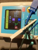
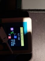
Afterthought. If you do have replacements, test a PNP just to know.
That's quite a difference, but let me study data sheets. If they're out of circuit, don't reinstall just yet. I might think of an experiment.
BTW, do you have replacements on hand?
Afterthought. If you do have replacements, test a PNP just to know.
Beta is supposed to be 200 to 700, so my suspicion remains. Double check collector vs. emitter hookup to your tester--- backwards would test reverse Beta, which is likely lower. Does your tester check any other parameters related to leakage? I'd be happy to continue regarding Q28 as the accused, but you might test Q26 as a confidence check of your measurements.
I see that the parts are obsolete, but I'm sure we can find subs.
I see that the parts are obsolete, but I'm sure we can find subs.
Hi Peter,
Back in post 107 (copied below), the problem with bias at base of Q31 was sticking out like a sore thumb, but I was too thick headed to spot it. 🙁😡 I was too obsessed with the bias not being enable to notice a problem was already evident, even with bias in shutdown. GRRR!
Sorry I didn't spot this earlier--- we could have bypassed at least some interim frustration.😳
Since both 2SC3324 and 2SA1312 are either problematic or obsolete, I recommend getting 10 each of Toshiba-recommended 2SC2713-GR,LF
and 2SA1163-GR,LF. Digikey seems to have plentiful stock, I didn't check Mouser. (I like Mouser, but DK seems to have a better search engine, so they are my habit.)
Whether you wish to pursue diagnosis now or wait for arrival of replacement parts, my suggested procedure would be the same:
Check bias at Q31 base pad, should be 0V. (I assume at this point Q31,Q28, Q26 are all out of circuit, Q30 still present.)
Remove the short across U1. Check bias at Q31 base pad, should be 0V.
Replace Q26. Check bias at Q31 base pad, should be 0V.
Replace Q28. Check bias at Q31 base pad, should be 0V.
Replace Q31. Check bias at Q31 base pad, should be 0V.
If at any of the replacement steps the 0.5 base bias reappears, measure the BCE voltages at newly replaced transistor.
Again, I'm sorry for leading you down alleys.
Back in post 107 (copied below), the problem with bias at base of Q31 was sticking out like a sore thumb, but I was too thick headed to spot it. 🙁😡 I was too obsessed with the bias not being enable to notice a problem was already evident, even with bias in shutdown. GRRR!
Sorry I didn't spot this earlier--- we could have bypassed at least some interim frustration.😳
Is U1 active, i.e. voltage between pins 3 and 4 near 0V, so amp is enabled? Nope, 27V. I assume this is because I don't have the ribbon cable J1 connected?
Shorting U1 as before, I get 35V bias instead of 60V.
Voltages across R43 and R76? 1.1/2.6
Voltages re ground:
Spreader voltages at collector and emitter of Q32 59.4/62.3/59.2
input at base Q31: 0.5V
feedback at base Q30: 2.1V
Output
supply voltages at U4, Pins 4 and 8: -15.0/0.0
U4 pin 1: 16V
All tested without the U1 jumper and J1 disconnected.
Since both 2SC3324 and 2SA1312 are either problematic or obsolete, I recommend getting 10 each of Toshiba-recommended 2SC2713-GR,LF
and 2SA1163-GR,LF. Digikey seems to have plentiful stock, I didn't check Mouser. (I like Mouser, but DK seems to have a better search engine, so they are my habit.)
Whether you wish to pursue diagnosis now or wait for arrival of replacement parts, my suggested procedure would be the same:
Check bias at Q31 base pad, should be 0V. (I assume at this point Q31,Q28, Q26 are all out of circuit, Q30 still present.)
Remove the short across U1. Check bias at Q31 base pad, should be 0V.
Replace Q26. Check bias at Q31 base pad, should be 0V.
Replace Q28. Check bias at Q31 base pad, should be 0V.
Replace Q31. Check bias at Q31 base pad, should be 0V.
If at any of the replacement steps the 0.5 base bias reappears, measure the BCE voltages at newly replaced transistor.
Again, I'm sorry for leading you down alleys.

Strange, but here they are. No U1 jumper:
Q31 base with Q26, then Q28, then Q31: 0.05
Q31 base with U1 jumper: 0 5V
I'm sorry, this didn't do is any good. I should've tested with U1 jumped.
Q31 base with Q26, then Q28, then Q31: 0.05
Q31 base with U1 jumper: 0 5V
I'm sorry, this didn't do is any good. I should've tested with U1 jumped.
Out of curiosity, with U1 jumped, I adjusted R53 to lowest resistance and measured the bias to TP4. It was 27V, instead of the 35V I got with it at 200ohm.
This is the opposite of what you were expecting per our earlier discussion.
This is the opposite of what you were expecting per our earlier discussion.
You're right--- nothing is as I expect. Now I'm not sure where we are.
I'm under the impression that the current limit resistors have been removed and output devices back in circuit--- i.e., circa posts 103 to 105. If this is indeed the case, adjusting R53 to 0 Ohms would have been very dangerous, as that would raise bias current to destructive levels. I hope this is not the case. In post 110 you reported spreader voltage had again collapsed after it appeared to have been working; I erred in not addressing the issue then, or at least cautioning you the leave bias adjusted to minimum. Instead I noticed front end was not working, a probable bias voltage issue. (As background, in a working amp, bias current and output bias voltage should be virtually independent issues.)
My personal MO is to not remove components unless necessary, as each change is an opportunity for errors on both removal and replacement. I don't intend to scold, but rather be a good mentor--- to teach a bit of theory and good troubleshooting practice as we go. I fear I'm failing, and I apologize.
So, let's reestablish where we are:
Are the current limit resistors removed? 60V rails reconnected to supplies? (Don't change anything--- just advise current configuration.)
Are Q18 and Q6 present or absent?
Are Q17 and Q7 present or absent?
Q14, Q3 ?
Any other output devices?
Thanks again.
No current limiting resistors.
All output devices are installed, as are all the other components I removed.
I adjusted R53 slowly and voltage dropped steadily, nothing smelled or got hot.
All output devices are installed, as are all the other components I removed.
I adjusted R53 slowly and voltage dropped steadily, nothing smelled or got hot.
Excellent! Then we're in a better place than I imagined. Were the 60V rails reconnected to the power supplies? 80V rails active at the amp?
The post 131 data is very useful. I don't fully understand, but it's useful.
Thanks for your patience while I ponder.
The post 131 data is very useful. I don't fully understand, but it's useful.
Thanks for your patience while I ponder.
#Strange, but here they are. No U1 jumper:
Q31 base with Q26, then Q28, then Q31: 0.05
Q31 base with U1 jumper: 0 5V
I'm sorry, this didn't do is any good. I should've tested with U1 jumped.
I'm still focused on the behavior at base of Q31 (= base of Q28). The results with the U1 jumper removed seem reasonable--- the bias is ~0v. But I'm baffled why the base of Q31 rises when U1 is jumpered. So would you measure the following voltages re ground, with U1 jumper installed:
Base Q26
BCE Q30
BCE Q31
junction R63,R64
BCE Q28
BCE Q26
junction R50,R51
Base Q29
Thanks again.
Would you dial R53 back to minimum bias for reduced worry? Thanks.
I'd like to explore the possibility that the Q31 bias path might be open.
Confirm that Q31 base remains at +0.5V. Then probe voltage to ground at both terminals of R57 and R58 at resistor bodies.
Thanks.
Edit: If there's about 22mV across R58, the bias path is probably intact.
Confirm that Q31 base remains at +0.5V. Then probe voltage to ground at both terminals of R57 and R58 at resistor bodies.
Thanks.
Edit: If there's about 22mV across R58, the bias path is probably intact.
Last edited:
Didn't have much time, but I got 0.5V at all 5 points, Q31, R57 & R58.
Voltage across was a bit weird and I want to test again. R57 said 1mv and R58 was variable between 1-5mv. I'll check it again when I get a chance, so don't take these readings as a sure thing.
Thanks again,
Peter
Voltage across was a bit weird and I want to test again. R57 said 1mv and R58 was variable between 1-5mv. I'll check it again when I get a chance, so don't take these readings as a sure thing.
Thanks again,
Peter
- Home
- Amplifiers
- Solid State
- Help!!! Dumb-a$$ ham first mistake content