Hi Peter,
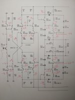
Since there doesn't appear to be much drop across R38 and R41, I suspect that the jumper across U1 pins 3 and 4 needs to be reinstalled. Another notation problem is I think you note measurement points with a small tick mark at the measured node and note the voltage nearby, but I need to know if the voltage is positive vs. negative, and the tick mark often leaves me uncertain about polarity.
Since you removed both Q6 and Q18, the bases of the output stages are probably floating. Would you tack a 10k resistor from the base of Q17 to ground. When you restore power, I anticipate the amp output voltage will then be near ground, but would you report what you find.
I suspect the front end voltages will change in response to these changes. Would you again advise what you observe, as you did in the marked up schematic above.
Thanks.
Thank you. Still plenty of mysteries.
With the amp output now measuring about 0V, I would have expected voltages at C26 to also be near ground--- ~30V is a suprise. Would you measure voltages at bases of Q18, Q17, Q7. Confirm amp output still about 0V and C26 voltage roughly as you reported above.
Thanks,
Steve
With the amp output now measuring about 0V, I would have expected voltages at C26 to also be near ground--- ~30V is a suprise. Would you measure voltages at bases of Q18, Q17, Q7. Confirm amp output still about 0V and C26 voltage roughly as you reported above.
Thanks,
Steve
Hello!
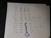
Bases:
Q18= 32.5
Q17= 31.6
Q7= 32.4
C26 32.5
Output at speaker terminals = 0.0
All referenced to negative speaker terminal.
The voltage at C26 reflects the bias issue... it's way too high to adjust correctly.
Bases:
Q18= 32.5
Q17= 31.6
Q7= 32.4
C26 32.5
Output at speaker terminals = 0.0
All referenced to negative speaker terminal.
The voltage at C26 reflects the bias issue... it's way too high to adjust correctly.
These voltages suggest something failed in the output stages. Start looking voltages at the output and poke your way back toward the base voltages above, eg. Q16 emitter, Q16 base, Q17 base. Somewhere along that path there should be a big jump in volts.
So how can there be +30V at Q16's emitter and 0V at the other side of R21, with only 0.33 ohms between? That "big jump in volts" would seem to be across R21.
Great question! I've been referencing the negative speaker output as "ground". As it's floating, I believe.
When I check again, 0.0v at the speaker terminals. However, L1, the coil, gets 31.1V but it's not getting to the positive speaker connections. Checking the relays... they aren't triggering when turning the speakers on/off! The ground path is fine, though
Could the current limiting resistors stop it from turning on the relays? Or could it be because Q6 is out of circuit?
Ok, this changes the picture significantly. So if you check voltage between L1 and base of Q17, it will be a at most a few diode drops. It's a good idea to check the voltages appearing at the 60V rails, but I doubt they are constraining the L1 voltage. Please confirm continuity from L1 to junction of R55 and R31.
I'll explore your recent data from the new perspective.
Thanks.
I'll explore your recent data from the new perspective.
Thanks.
Earlier, I was so alarmed by the difference between Q18 and the assumed 0V at output that I hadn't studied the post 162 voltages. So now, I've found some issues that suggest damaged devices.
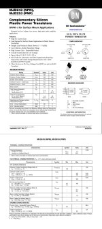
Readings at post 162 indicate -71V at base of Q24 and -62.6V at emitter. That suggests failed Q24, since there should be only 0.6V between base and emitter. Another problem is present at Q38 where base is +68 and emitter is +59V; in this case the base-emitter is reverse-biased by 9V. Double check that the correct device types were installed with proper insertion.
After replacements, please again report voltages, but leave amp in semi-disabled state. We'll want some additional tests before reconnection.
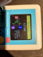

How can Q23 have a collector value of 2.2 and Q35 have 0.4 when they have the same emitter and base values?
I'm guessing that the Ic number means that the tester is measuring hfe with collector current driven to 6.1mA. I'm not spotting the 2.2 and 0.4 numbers; can you advise where to find them?
I think the transistors are probably acceptable. I suspect the amplifier may be oscillating, thus producing voltage readings that can't be trusted. I suggest reinstalling the transistors and doing quick confirmation that the output voltages are about the same as before.
If you have a 'scope, I'd advise you confirm oscillations, but I if I remember, you don't have one.
I'd still like to get bias to behave, as that would confirm front end, allow testing of bias spreader, and aid scrutiny of the outputs--- all with minimal risk. To that end, would check servo output at U3A, pin 1. Its voltage should be near the positive +16V rail. (Also, confirm presence of -16V raii.) Then disconnect R55 and again look at output at L1. With luck, it will now read 0V.
Have you had a chance to think about the Q23 & Q35 collector values?
U3 pin 1 = 13.9. the rails read +/- 14.9 with R55 connected.
L1 = 37.5V with R55 disconnected.
U3 pin 1 = 13.9. the rails read +/- 14.9 with R55 connected.
L1 = 37.5V with R55 disconnected.
Well, shoot. I was hoping opening the R55 path would stop oscillation. Oscillation may not even be the explanation. No scope available, right? I'll have to noodle a bit.
The observed voltages on Q23 and Q35 are governed by the loading presented at their respective collectors. Both Q23 and Q35 implement constant current sources, each delivering about 4.4mA. Note the different emitter voltages at Q30 and Q31 vs. those at Q26 and Q28. They correspond to the differing collector voltages you ask about.
A central question is why the input pairs don't bias to 0V. That's the goal of the most recent experiment.
Just going through what originally happened again... I probably shorted the 60v and 80v rails around Q15 & TP4.
result = blown D25. What else could've been damaged? Looking through the path, I looked in the R73/R48 area and noticed R48 looks to be slightly discolored. I removed both and checked them, they're both measuring the same; 12k. Also checked C25 just in case as it's right next to R43... it measures fine also.
R47/R72 both measure fine
R43/R76 both measure fine
R2/R23 both measure fine
It's your suspicion not l more the 80v or 60v paths?
At this point, I have no specific suspect. The voltages reported in post 162 were very strange, especially at Q24 and Q28. It's unclear if they are cause or symptoms of damage still existing in the output section.
So to localize the damage, let's more definitively separate input section from output. Remove Q18. I believe Q6 and R55 are already absent, but verify. Connect a 10k resistor from base of Q17 to ground. Tack temporary shorts across C21 and C22. When you apply power, the amp output at L1 should bias to 0V and base at Q17 should also be at 0V. +/- 60V rails should charge slowly toward nominal. Please advise issues if are not as indicated.
Servo amp U3A should read 0V at its output. Please report voltages at bases of Q30 and Q31. Check voltages at C26; they might be stuck at one of the supply rails, which could be an encouraging sign. If stuck at a rail, I'll suggest further checks when I've seen what you find. But if still stuck in the vicinity of 30V, would you again report interstage voltages as you did in post 162.
Thanks again.
- Home
- Amplifiers
- Solid State
- Help!!! Dumb-a$$ ham first mistake content