Also, R53:
40ohm
200ohm
C26 to ground:
0.0
62.8
Q8:
0,0,0
61.1, 60.8, 61.8
Q10:
0,0,0
62.5, 63.4, 62
Apparently the bad channel doesn't turn off everything left off Q17.
Also, R55 was disconnected a long time ago.
40ohm
200ohm
C26 to ground:
0.0
62.8
Q8:
0,0,0
61.1, 60.8, 61.8
Q10:
0,0,0
62.5, 63.4, 62
Apparently the bad channel doesn't turn off everything left off Q17.
Also, R55 was disconnected a long time ago.
Last edited:
Hi Peter,
I'm sorry I'm so slow to respond. Life intervenes...
I annotated the partial schematics with your measured voltages and will post them for comparison, tomorrow. (Late here.) An interesting phenomenon present in both working and failed units is the behavior of the emitter voltages at Q11 and Q9. In all four cases, the base-emitter junctions are reversed biased. The only explanation I can guess is that bias currents are so small the meter load currents to ground are sufficient to generate reverse biasing.
I suggest connecting the reference lead of the meter to the positive rail and probing the base and emitter voltages of Q11 to see if Q11's b-e junction then shows expected forward bias. If Mute were released in the good channel, I think this phenomenon would disappear.
The other glaring phenomenon in the problem channel is the roughly 60V on the collector of Q11. This implies 0.3W dissipation in both R73 and R48. Assuming the center ground path is intact, these resistors should be getting HOT! Are they? And it they are hot, where is the ~5mA+5mA current coming from? And how does this square with the small currents seemingly implied in the previous paragraph?
I think the problem lurks in this area.
TTYL
I'm sorry I'm so slow to respond. Life intervenes...
My apologies, as I intended to type left of Q37 rather than Q17, but didn't notice the error. In Mute, the balanced differential input stages are unbiased by virtue of having their current sources disabled. Later stages pass minimal current when the amp is Muted.With no signal, Q9 and Q11 should be near 0V, irrespective of Mute. In Mute, all circuits left of Q17 are biased off and won't pass audio.
I annotated the partial schematics with your measured voltages and will post them for comparison, tomorrow. (Late here.) An interesting phenomenon present in both working and failed units is the behavior of the emitter voltages at Q11 and Q9. In all four cases, the base-emitter junctions are reversed biased. The only explanation I can guess is that bias currents are so small the meter load currents to ground are sufficient to generate reverse biasing.
I suggest connecting the reference lead of the meter to the positive rail and probing the base and emitter voltages of Q11 to see if Q11's b-e junction then shows expected forward bias. If Mute were released in the good channel, I think this phenomenon would disappear.
The other glaring phenomenon in the problem channel is the roughly 60V on the collector of Q11. This implies 0.3W dissipation in both R73 and R48. Assuming the center ground path is intact, these resistors should be getting HOT! Are they? And it they are hot, where is the ~5mA+5mA current coming from? And how does this square with the small currents seemingly implied in the previous paragraph?
I think the problem lurks in this area.
TTYL
Last edited:
Yes, R48/R73 are slightly discolored but I haven't noticed them getting too hot. They look similar on the good amp, so I'll replace them with higher wattage resistors.Just going through what originally happened again... I probably shorted the 60v and 80v rails around Q15 & TP4.
result = blown D25. What else could've been damaged? Looking through the path, I looked in the R73/R48 area and noticed R48 looks to be slightly discolored. I removed both and checked them, they're both measuring the same; 12k. Also checked C25 just in case as it's right next to R43... it measures fine also.
R47/R72 both measure fine
R43/R76 both measure fine
R2/R23 both measure fine
It's your suspicion not l more the 80v or 60v paths?
Perhaps they have failed. They should be hot to touch. Together they would be drawing about 10mA from the positive rail. What voltage drop do you see across R23? Compare with the good channel.
Q11, positive probe on positive rail, probing with negative:
87.6, 87.8, 87.5.
Same with mute on or off.
87.6, 87.8, 87.5.
Same with mute on or off.
R23:
2v
4.5v
Across R48:
61v
Across R73:
64v
... and yes, these are warm. These are 0v on the good amp.
Another oddball, across these diodes:
(Good amp on top)
D14:
83
142(!)
D14
83
18(also !)
Diode string from Q24-R14:
-86.6/-87
-85.4/-86.4
-85.2/-85.5
From Q37-R14:
86.5/84.3
85.9/83.8
85.2/83.2
2v
4.5v
Across R48:
61v
Across R73:
64v
... and yes, these are warm. These are 0v on the good amp.
Another oddball, across these diodes:
(Good amp on top)
D14:
83
142(!)
D14
83
18(also !)
Diode string from Q24-R14:
-86.6/-87
-85.4/-86.4
-85.2/-85.5
From Q37-R14:
86.5/84.3
85.9/83.8
85.2/83.2
At first glance, these similar voltages seem to confirm my theory that the reverse-biased b-e junctions were the result of meter load resistance currents to ground. But on closer inspection they made no sense, as I would anticipate only a few volts showing on the rail referenced voltmeter, but you find nearly the entire supply voltage. This is inconsistent with Q11 voltages in post 301; and the Q11 voltages seem inconsistent with there being 60V at R73 re ground.Q11, positive probe on positive rail, probing with negative:
87.6, 87.8, 87.5.
Same with mute on or off.
I suggest printing a copy of the sub-circuit PDF in post 300 and recording the observed voltages on the schematic. Because the most recent measurements were the most mysterious, I suggest again taking the readings with positive meter probe on the positive rail, eg at any convenient point tied to Q37 collector. Having done that, I would connect meter to ground and probe at same points and confirm sensical, consistent readings.
Last edited:
Hi Peter,
Please forgive me for taking so long to respond. Your amp's problem is vexing and life intervened... Sorry excuses.
I believe I erred "big-time" when I failed to consider how current through R13 affects bias across R76. With corrected perspective, the measurements of the good channel in muted state seem reasonable.
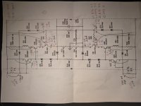
I'm attaching a marked-up partial schematic of predicted voltages in the muted state. Each arrow depicts an expected voltage noted at the head of the arrow, with tail of arrow indicating the placement of the meter's black lead.
I suggest measuring each arrow-identified node and noting the observed voltage, either on the diagram or in tabular form. I've blindly assumed all diode drops and transistor Vbe are 0.6V, so estimates are only approximate. I believe actual readings will be within a couple tenths V re predictions. I would characterize the working channel for reference, then compare voltages of the defective channel. I think the defective part will show significantly different voltages, most likely at Q38 or Q9. Specifically, why does the defective channel present many volts at Q11 collector rather than 0V as it should?
A few other notes:
Operating current in Q37 and Q24 is roughly p-p supply voltage (less a few diode drops) divided by R14, about 5mA. These transistors have Beta lager than 200 and get their base current via R71 and R46. Consequently, R71 and R46 should drop only tens of mV.
In similar manner, current through R76 and R43 is roughly p-p supply voltage (less a few diode drops) divided by R13, about 7.65mA. R76 and R43 are both 150R, 1% so should measure equal drops of about 1.15V--- enough to ensure Q38 and Q25 are biased off.
There should be very little drop across R72 and R47.

Please forgive me for taking so long to respond. Your amp's problem is vexing and life intervened... Sorry excuses.
I believe I erred "big-time" when I failed to consider how current through R13 affects bias across R76. With corrected perspective, the measurements of the good channel in muted state seem reasonable.
I'm attaching a marked-up partial schematic of predicted voltages in the muted state. Each arrow depicts an expected voltage noted at the head of the arrow, with tail of arrow indicating the placement of the meter's black lead.
I suggest measuring each arrow-identified node and noting the observed voltage, either on the diagram or in tabular form. I've blindly assumed all diode drops and transistor Vbe are 0.6V, so estimates are only approximate. I believe actual readings will be within a couple tenths V re predictions. I would characterize the working channel for reference, then compare voltages of the defective channel. I think the defective part will show significantly different voltages, most likely at Q38 or Q9. Specifically, why does the defective channel present many volts at Q11 collector rather than 0V as it should?
A few other notes:
Operating current in Q37 and Q24 is roughly p-p supply voltage (less a few diode drops) divided by R14, about 5mA. These transistors have Beta lager than 200 and get their base current via R71 and R46. Consequently, R71 and R46 should drop only tens of mV.
In similar manner, current through R76 and R43 is roughly p-p supply voltage (less a few diode drops) divided by R13, about 7.65mA. R76 and R43 are both 150R, 1% so should measure equal drops of about 1.15V--- enough to ensure Q38 and Q25 are biased off.
There should be very little drop across R72 and R47.
Hello Steve! Thanks for the response. I hope all is well with you.
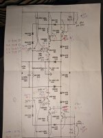
It seems we're getting -3.5v instead of -1.1v at R76. It measures 149.8ohm, as do the others. Could something else be adding voltage on that side of the resistor?
Please see attached.
It seems we're getting -3.5v instead of -1.1v at R76. It measures 149.8ohm, as do the others. Could something else be adding voltage on that side of the resistor?
Please see attached.
Attachments
It seems we're getting -3.5v instead of -1.1v at R76. It measures 149.8ohm, as do the others. Could something else be adding voltage on that side of the resistor?
I think your speculation is correct. 3.5V/150R implies about 23.3mA. Your measurements show 63V across R73 and 61V across R38, which is about 5.25mA and about 5.08mA respectively. These currents plus the 7.65mA though R13 account for almost 18mA. There may be currents drawn from the bias spreader providing the rest. Presumably these currents are flowing through R76; the bigger questions are what is the path of this current and why aren't these currents blocked by back-biased transistors (Q38)?
If I interpret correctly, you observe -1.1V at the base of Q38, and will presumably find the same voltage at emitter of Q37 if traces are intact. But the Q37 emitter is expected to be about -0.6V. Is it possible that Q37 has been replaced and is now a Darlington transistor? Similar questions arises at Q24.
If Q37 and Q24 are proper parts, I would remove both Q38 and Q25, and then remeasure voltages. With them absent, Q37 and Q24 b-e voltages should drop about 0.6V, and Q11 and Q9 collectors should be at ground. But what do you find?
Thanks.
Last edited:
- Home
- Amplifiers
- Solid State
- Help!!! Dumb-a$$ ham first mistake content