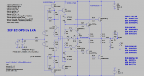
IMO the 3EF EC is just one of the many variations on the HEC in posting #52, see image below, where effectively one resistor has been removed (1Gig) and one shortened (0.01R).Btw, above is not HEC (Hawksford EC), K200 is a HEC implementation. Basically it is a 3EF preceded by a buffer stage. I compared the distortion profile with and without EC. Distortion reduction at low powers (up to 50W/4R) is significant.
Around the lower Op-amp, gain from the minus input has been reduced accordingly from 1 to 1/2 et voila, there's your implementation of the 3EF EC.
I'm fine when you prefer to call this EC instead of HEC.
I didn't have the time already to look at the distortion at lower output voltages, I will certainly do, but I first concentrated on the reason why at 100W/4R the non EC buffer performed so much better as the 3EF EC.
Keeping all currents the same in the three stages, first thing I did was to replace the transistors by Op-amps.
This showed absolutely no difference at all in the THD, proving did you did a perfect job with the transistors.
Next thing I did was to replace the emitter follower of the second stage, and oh man, THD dropped from 314ppm to 6ppm, and especially H3 went from 309ppm to 1ppm, a 47dB improvement !!
So it's not the EC amplifier part but the second emitter follower causing the difference between 3EF EC and 3EF NonEC.
I'm still working on a work around for this, but a darlington did not give any benefit.
Keep you informed.
Hans
Attachments

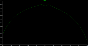
Wingspread simulation also shows that the most corrected region is the cross-over region. The gain variation at large signals is less when straight 3EF is used.
(referring to the schematics in post 57)
(referring to the schematics in post 57)
Attachments
Last edited:
I did not succeed bringing the distortion down at 100W/4R, no matter what I used for the second EF stage, darlingtons, Mosfets, whatever.
So this stage wants to be driven from a low source resistance to keep distortion low.
That's why I switched to a completely different, much simpler topology, that keeps ALL distortions under control by directly comparing the input to the output signal.
I have used a single op-amp, giving ppm distortion.
figure resp. are for:
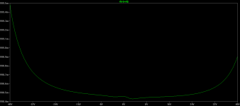
100Watt/4R
THD 3 ppm
H3 2 ppm
10Watt/4R
THD 7ppm
H3 6ppm
So yes LKA you are absolutely right, low levels are affected more by cross-over than high output levels.
The Op-amp used can be any low distortion version, like the LM4562, powered by a floating supply attached to the output.
The power of this FDR (Feedback Distortion Reduction) is that you don't have to tune any resistors, straightforward and simple.
This is the solution that I am using, that's why I was interested in comparing it to a HEC.
Hans
So this stage wants to be driven from a low source resistance to keep distortion low.
That's why I switched to a completely different, much simpler topology, that keeps ALL distortions under control by directly comparing the input to the output signal.
I have used a single op-amp, giving ppm distortion.
figure resp. are for:
100Watt/4R
THD 3 ppm
H3 2 ppm
10Watt/4R
THD 7ppm
H3 6ppm
So yes LKA you are absolutely right, low levels are affected more by cross-over than high output levels.
The Op-amp used can be any low distortion version, like the LM4562, powered by a floating supply attached to the output.
The power of this FDR (Feedback Distortion Reduction) is that you don't have to tune any resistors, straightforward and simple.
This is the solution that I am using, that's why I was interested in comparing it to a HEC.
Hans
Attachments

Jan,
I could not Quote your question, it showed a "multiquote", what's that ?
Anyhow, here is your answer.
In the two models I presented in posting #52, the mathematical model and an example of an implementation, input minus output can be theoretically brought to zero and only depends on the accuracy of tuning the resistors, which comes very precise.
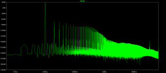
When done for a real amplifier, you see al sorts of higher harmonics, most notably H3.
So there is no need to subtract input from output, just look at H3.
The advantage of doing that is that small gain errors, not contributing to harmonic distortion, are neglected.
Hans.
I could not Quote your question, it showed a "multiquote", what's that ?
Anyhow, here is your answer.
In the two models I presented in posting #52, the mathematical model and an example of an implementation, input minus output can be theoretically brought to zero and only depends on the accuracy of tuning the resistors, which comes very precise.
When done for a real amplifier, you see al sorts of higher harmonics, most notably H3.
So there is no need to subtract input from output, just look at H3.
The advantage of doing that is that small gain errors, not contributing to harmonic distortion, are neglected.
Hans.
Hi Hans. As you are dealing with op amp version of Hec, can try my way , upon LKA's 3×EF ? described here Simple high power BJT/MOSFET G=0.6db output with Hawksford error corrector .
bellow is Spice model of ultra low distortion/noise CFA opamp.
My simulator is Tina , measurments are different hence uncomparable.
Hayk
Hayk,
I'll come back in your own thread.
Hans
Jan,
I could not Quote your question, it showed a "multiquote", what's that ?
Anyhow, here is your answer.
In the two models I presented in posting #52, the mathematical model and an example of an implementation, input minus output can be theoretically brought to zero and only depends on the accuracy of tuning the resistors, which comes very precise.
When done for a real amplifier, you see al sorts of higher harmonics, most notably H3.
So there is no need to subtract input from output, just look at H3.
The advantage of doing that is that small gain errors, not contributing to harmonic distortion, are neglected.
Hans.
Hans, I was referring to your statement that you couldn't see the 5kHz 'error signal' on Vout being a measure of how well it worked.
But if you show Vout-Vin, you will better see any remaining 5kHz. I wonder what that would show, as it is a much more sensitive measurement.
Jan
hans, why you do not try your error corrector post 52, using bootstrapped supply referenced on the output? With mine I get 0.006% with outputs biased 15ma/pair. A year ago , not knowing about Hawksford , I created an error corrector with discreet transistors for five TDA7294 outputs in parallel 200w/8ohm. Before all explode, it worked very fine. On my pad I have a working sketch, I'll post it tomorrow .
Low driving impedance is not mandatory (rather its "constant" value in audio band). Here input imp is 10k, corresponding resistors R4,R6 modified.
I get with this 0.046% ,30V 10khz 4ohms.
In the above EC implementation (and Cordell also) the error amplifier corrects the output stage only (not driver nor predriver). K200 implements error correction for the driver+outputs. The resulted distortion for large signal (100W/4R/10k) is 20dB better (equal H2 H3).
Attachments

Last edited:
Hans, I was referring to your statement that you couldn't see the 5kHz 'error signal' on Vout being a measure of how well it worked.
But if you show Vout-Vin, you will better see any remaining 5kHz. I wonder what that would show, as it is a much more sensitive measurement.
Jan
Jan,
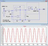
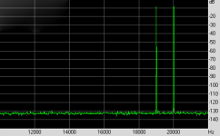
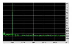
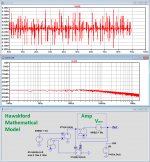
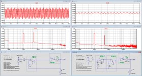
Here you are as promised, the difference between In and Output of the Hawskford mathematical model and an implementation in two versions.
In the Hawskford math model, I only used mathematical functions, to avoid any frequency dependancy.
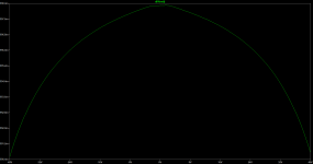
An can be seen in the first image below, In and Output are equal for the full 100% even though a Amp with 100% 5Khz distortion was used.
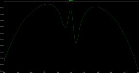
The second image shows the the result for an implementation with real components.
The GBW of the Amp made no difference in the error correction, the one used had a GBW of 1Mhz.
For the encircled active correction part, the two buffers that where used were having resp. a GBW of 1Mhz and 100Mhz.
That makes it clear that the achieved correction residue, resp. 33mV and 0.33mV rms, is directly proportional to the used BW of these components.
Hans
Attachments
Exactly! Years ago I spend a lot of time calculating and graphing these issues in MathCad.
The short of it is that both the accuracy of your summing/correcting element and its bandwidth have a direct relation to the amount of error correction possible.
Say you have an error E at a certain frequency. If you want to decrease the error to, say, 1/100 of E, there are two requirements for the error correction element. You must have a minimum magnitude accuracy but also a minimum phase accuracy.
In this example, its magnitude accuracy must be at least 1/100 or 1%. Secondly, to have the required phase accuracy, its bandwidth must be 100 times the frequency of the E you want to correct.
So, if you want to decrease the distortion at 10kHz by 40dB, your magnitude accuracy of the ec element must be at least 1%, and its bandwidth at least 1MHz.
When all is said and done, that good old negative feedback doesn't seem such a bad deal anymore ;-)
Jan
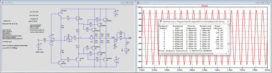
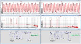
And just for completeness, here the FDR (Feedback Distortion Reduction) solution.
At first sight the performance is identical to the Hec topology version with 100Meg GBW amps in the correction, but there are a number of essential differences:
1) With FDR the correction takes place over the whole path from input to input, where Hec needs to start correcting somewhere within the Amp.
2) There is no need for tuning any component other than the feedback cap around the op-amp for stability reasons
3) Automatically the Amp's output offset is equal to the Op-amp's Voffset, no servo or whatever tuning will be additionally needed.
4) When even more suppression of distortion is needed, a second nested op-amp can be inserted, see the image at the right, where the 5Khz distortion has been reduced for another 50dB, and is no longer visible in the differential residue signal of Input minus Output.
Hans
Attachments
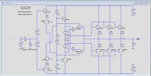
Rushed Hec

by Rushing, I get current addition of the Hec. This is a quick trial to see how it works. I get for 8 ohm 0.0007% for 30Vp 10khz vs 0.0065% for my opamp bootstrapped version.
May be CIR Pspice format can be imported by LT, see attached.
Hayk
by Rushing, I get current addition of the Hec. This is a quick trial to see how it works. I get for 8 ohm 0.0007% for 30Vp 10khz vs 0.0065% for my opamp bootstrapped version.
May be CIR Pspice format can be imported by LT, see attached.
Hayk
Attachments

I've noticed, most people use 8R load. I prefer 4R, 8R is a lite load, handy for nicer thd numbers. 🙂
K200v3 bipolar buffer THD 30Vp 10kHz
4R - 0.0017%
8R - 0.0006%
K200v3 bipolar buffer THD 30Vp 10kHz
4R - 0.0017%
8R - 0.0006%
Hayk,
What is the function of the circuit in the left lower corner.
It has only an input J1 but no output ??
Hans
What is the function of the circuit in the left lower corner.
It has only an input J1 but no output ??
Hans
- Home
- Amplifiers
- Solid State
- HEC amp