Can you produce us similar THDvPOWER (or/and THDvFREQ) graph for K200 as in post #96 ?
Two images, one at 10Khz and one at a more meaningful 2Khz.
Both for 4R and 8R.
Hans
Attachments

Two images, one at 10Khz and one at a more meaningful 2Khz.
Both for 4R and 8R.
Hans
nice, thx
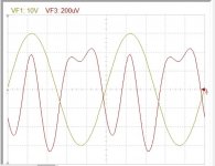
The problem of stability was due to driver transistors spice model not compatible with Tina. I replaced them with MJE 15032/33 as well as BD139/140 the result is shown bellow. the distortion is 0.0043% that Tina measures and can be seen on the scope. So with the precedent drivers it can be between 0.0013 and 0.0043%. This is only with Rush. I will go back to the roots ,and try out the Hec only without outputs biased, to see if I can get similar result as with my reactor.
Attachments
Last edited:
Hayk,
With all respect, but IMO you are turning LKA’s thread completely upside down with totally different designs.
Probably better to do this in another thread.
My contribution was just to show that the HEC concept is nice, but relatively complex to get optimal results compared to other EC schemes.
But compliments to LKA, he did a great job.
Hans
I would like to, but the title of the thread is a general HEC amp. I can not start another thread with the same title. But as it should I switch to my Hawksford.
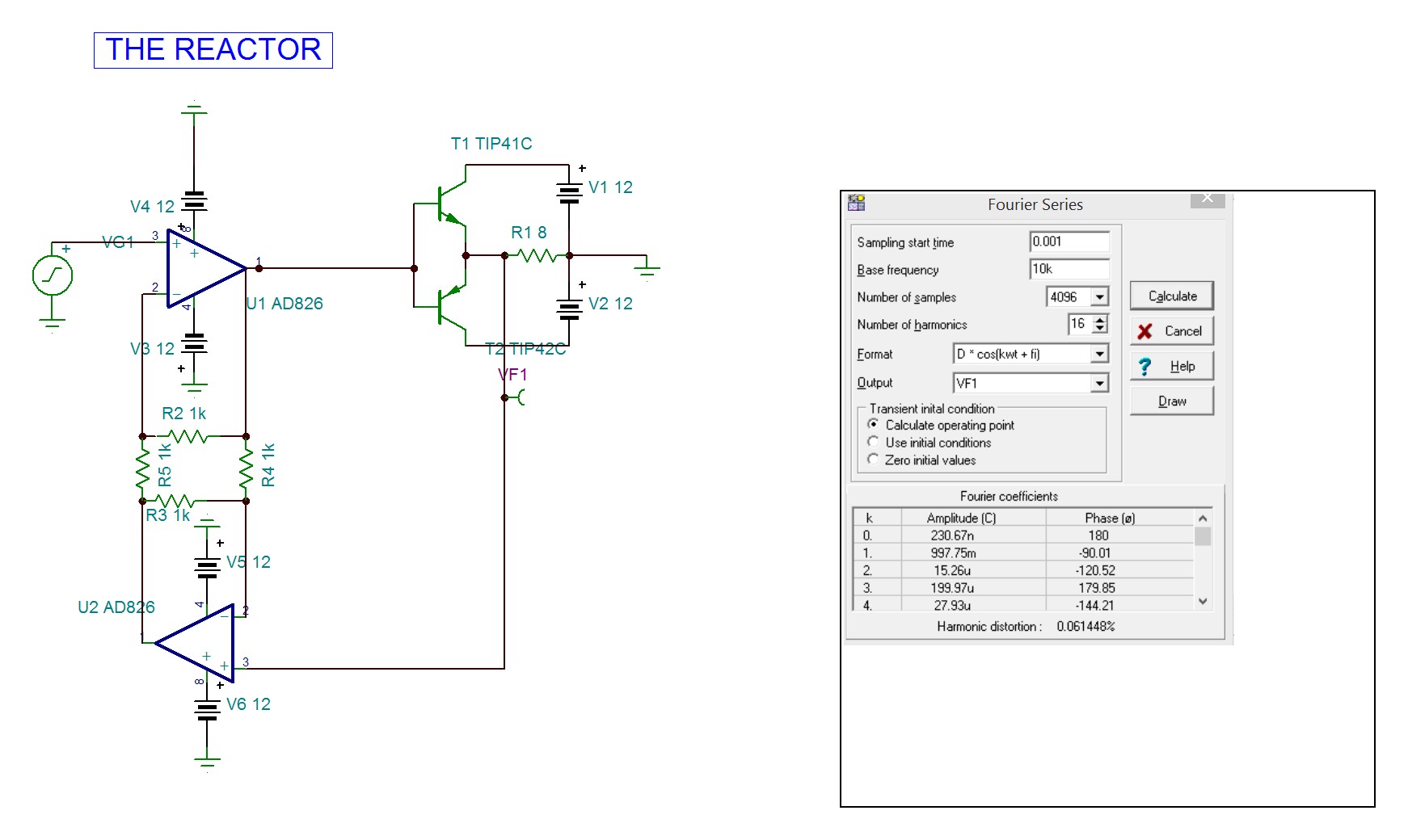
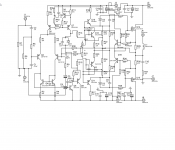
Here is a circuit I did a while back using HEC, see below and attachment, also my take on the Quad current dumping amplifier, its called COD because its Complementary Output Dumpers and also for fish puns.
FET amplifier
FET amplifier
Attachments
Last edited:
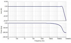
A small improvement. Successfully applied TPC compensation, I haven't seen it anywhere yet. 😉
50W/4R => THD20k falls from 0.000930% to 0.000481%


50W/4R => THD20k falls from 0.000930% to 0.000481%
Add an additional 220pF between the collector and base of Q14 and Q15.
14 compensation capacitors 😱
14 compensation capacitors 😱
Better this way, one capacitor less.
The square wave response has overshoots, as is characteristic of TPC.

The square wave response has overshoots, as is characteristic of TPC.
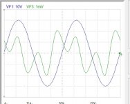
the K300 HEC buffer, TPC is not yet deployed


The measurement confirmed the simulation. Distortion at higher frequencies is lower with TPC up to the level approx 50W/4R

To mention a subjective experience from my side and based on just one single Class A amp was that when applying TPC, the already very low distortion started to become less as from 1Khz up to 20Khz but the perceived sound reproduction became cold and less involving.
Hans
Hans
Member
Joined 2021
Schematic please
- Home
- Amplifiers
- Solid State
- HEC amp