I've noticed, most people use 8R load. I prefer 4R, 8R is a lite load, handy for nicer thd numbers. 🙂
K200v3 bipolar buffer THD 30Vp 10kHz
4R - 0.0017%
8R - 0.0006%
Hi LKA,
Those are fantastic figures, but so far as a result from LTSpice I presume ?
Have you already had the opportunity to measure these figures live ?
About the difference between 8 and 4 Ohm, I still have live recordings of IM distortion of 80Watt@8R and 160Watt@4R (notice the different freq scales).
And yes, 4R gives the Amp more work to do resulting in worse figures.
With LTSpice, the 80Watt/8R version was spot on, but I got the third image for 320Watt@2R that is even better as my 160Watt@4R measurement.
So the proof of the pudding .....
Hans
Attachments


Last edited:
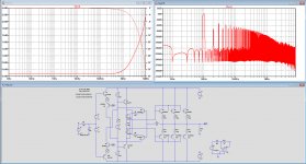
Hi Hans, The aux. circuit extracts the derivative of the output to magnify the crossover aberrations.
I switched to my non-switching version. Not only the circuit is stable ,it has an astonishing transient.
The error corrector can be very precisely adjusted, if under, the output is less than the generator, if over, than the output is more than the generator with negative input impedance. Strangely, it requires a symbolic inductor in feedback ,even 0 henry or else the distortion goes from 0.0072%to 0.01%. If the inductor is replaced by a 100 ohm resistor and a high value grounding resistor to reduce the feedback, than the output goes over amplifying . This circuit can also include current feedback.
As this version is non-switching, and the Hec is there for linearizing the crossover, I will post the final version, on my thread about this particular subject.
Hayk
Attachments

Hi LKA,
Those are fantastic figures, but so far as a result from LTSpice I presume ?
Have you already had the opportunity to measure these figures live ?
Hans
Yes, those numbers are from the simulator.
I've measured 0.003x for 28Vp/4R/10k (approx twice of simed)
Attachments
Hi LKA, can you export your K200 in format .LIB or .CIR .Tina distortion measurement is not straight forward, it needs to adjust a certain delay and verify with more delays that the value is mostly probable. With AKSA , we tried on the same circuit measurments, he never got as low value as me with Tina.
Hayk
Hayk
Hayk,
I modified the according according to your last version with only one output pair.
The max Sinewave input voltage is 2Volt. Everything above and oscillations are there at 15Mhz.
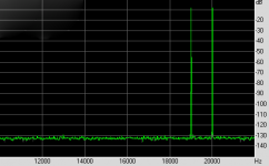
For 2Volt, I have shown the FFT.
Tell me what I'm doing wrong, because this cannot be what you have in mind.
Hans
I modified the according according to your last version with only one output pair.
The max Sinewave input voltage is 2Volt. Everything above and oscillations are there at 15Mhz.
For 2Volt, I have shown the FFT.
Tell me what I'm doing wrong, because this cannot be what you have in mind.
Hans
Attachments
Yes, those numbers are from the simulator.
I've measured 0.003x for 28Vp/4R/10k (approx twice of simed)
Hi LKA,
Thanks for your image, you have published this before.
1) In posting #71, you have shown a 100Watt/10Khz measurement having a distortion of the buffer alone of ca. -66dB, or 0.05%.
2) In the image you just gave, I see a measured 0.005% or -86dB at 100W@10Khz for the non GNFB situation, so this must be mainly distortion from the K200V3, right ?
3) But in posting #78, you mention 0,0017% distortion at 100Watt@10Khz or almost -96dB from LTSpice.
Those figures are 30dB apart, so I hope can understand that I'm a bit lost in your figures to understand what is what.
My interest is mainly in the performance of the buffer with HEC.
Hans
Hayk,
Sorry, your suggestions do not make any difference at all.
Keeps oscillating and the FR only changes hardly at all.
What spice models are you suspecting ? I could change for other transistors.
No possibility to export as .Cir or .Lib,
Hans
Sorry, your suggestions do not make any difference at all.
Keeps oscillating and the FR only changes hardly at all.
What spice models are you suspecting ? I could change for other transistors.
No possibility to export as .Cir or .Lib,
Hans
Hi LKA,
Thanks for your image, you have published this before.
1) In posting #71, you have shown a 100Watt/10Khz measurement having a distortion of the buffer alone of ca. -66dB, or 0.05%.
2) In the image you just gave, I see a measured 0.005% or -86dB at 100W@10Khz for the non GNFB situation, so this must be mainly distortion from the K200V3, right ?
3) But in posting #78, you mention 0,0017% distortion at 100Watt@10Khz or almost -96dB from LTSpice.
Those figures are 30dB apart, so I hope can understand that I'm a bit lost in your figures to understand what is what.
My interest is mainly in the performance of the buffer with HEC.
Hans
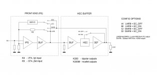
I hope attached picture helps to clarify things.
"1) In posting #71, you have shown a 100Watt/10Khz measurement having a distortion of the buffer alone of ca. -66dB, or 0.05%."
I guess you mean post #54.
This is a completed amp (chassis, SSR, etc) which I name KLA200.
Measured option A and B.
A/ 100W/4R/10k = 0.03% (LNFB, buffer without EC)
B/ 100W/4R/10k = 0.004% (LNFB, buffer with EC)
"2) In the image you just gave, I see a measured 0.005% or -86dB at 100W@10Khz for the non GNFB situation, so this must be mainly distortion from the K200V3, right ?"
Post #83.
Bare modules on the bench (no SSR protection)
B/ 100W/4R/10k = 0.0035% (LNFB, buffer wit EC)
D/ 100W/4R/10k = 0.00045% (GNFB, buffer with EC)
"3) But in posting #78, you mention 0,0017% distortion at 100Watt@10Khz or almost -96dB from LTSpice."
Yes, this is a simulated option B
Attachments
LKA,
Thank you for your extensive explanation.
As I mentioned, my main interest was for the HEC buffer.
You made clear that LTSpice shows 17ppm versus a 35ppm distortion measurement, both for the HEC buffer at 100Watt@10Khz.
Still confusing is the 10Khz spectrum that posting #71 is showing for the HEC buffer.
Hans
I did had some ringing , but replacing L1 by 330 ohm and higher input C to 80pf it almost resolved. Can LT import .CIR ?
Attachments
Last edited:
I installed LT, send me your file . With file/open/schematics choose Netlist/.CIR.
Attachments
Last edited:
LKA,
Still confusing is the 10Khz spectrum that posting #71 is showing for the HEC buffer.
Hans
yes, the buffer alone. you can try it yourself, the sim file is below
Attachments
Last edited:
Hans, I will restart back the design after learning from this sketch. As LKA stated the Hec corrects only the output , not the precedent stages. So I will first design a driver stage with Rush feedback, maybe in class A, than add the output stage along with its Hec, by this each feedback operates independently. After to see what can be done.
Hayk,
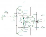
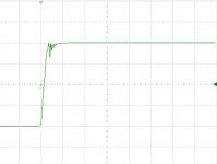
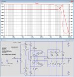
I didn't want to further take the route of going up and down between LTSpice and your Tina, so I tried a few things myself and got the thing stable.
Using the 80pF at the input that you suggested, and adjusting the idle current to the same 75mA that LKA is using.
I switched the BC550 and BC560 for the 2N5401 and 2N5550, and had to place 100nF caps par. to the 1N4148 diodes, see first image below.
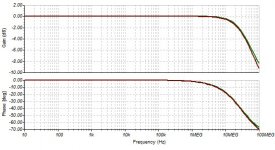
Looking at the 9.5dB peak in the FR response with 80pF at the input, it's obvious that 15Mhz is the frequency where the thing likes to oscillate.
Without this cap, the peak is even close to 20dB.
So you must definitely try to get this peak down.
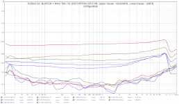
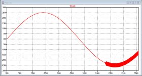
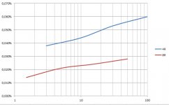
Anyhow, I could now measure distortion for 4R and for 8R, which is shown in the second image with Watts on the horizontal axis.
Hans
Attachments
yes, the buffer alone. you can try it yourself, the sim file is below
Thank you for the model.
In posting#71 I just saw a distortion at ca -66dB, but missed the +26dB of H1 that had to be added, that would immediately have prevented the confusion.
Everything is clear now.
As a side remark: I did not you use your .txt file but used "Cordell models.txt" and "Cordell-models.txt".
Obviously there are slight differences with your .txt because THD in my case with 28.3V applied was even 14ppm, mainly because H2 dropped quite a bit.
But anyhow, I'm always surprised how close the Sim and the real thing are for everything above -120dB.
Hans
Hans, I totally review the principle of my circuit. For now I modeled with great success the output stage with Rush only ,to make it work similar principle for non-switching. It is as good as I have done by a pair of AD8008 ,0.016% at the output but 0.0001% at the unloaded driver . The Hec now will pull up the impedance of the output stage and unload back the driver and equate the output to that of the driver. I'll post the circuits on my non-switching thread.
I have now LT from Analog Device , can you post your model in .asc, please, I can start learning usefully.
I have now LT from Analog Device , can you post your model in .asc, please, I can start learning usefully.
Last edited:
Hans, I totally review the principle of my circuit.
I have now LT from Analog Device , can you post your model in .asc, please, I can start learning usefully.
Hayk,
It's good that you review the principle, because I just measured the straight 3EF buffer without any form of feedback, and THD was almost the same as your solution.
So it definitely needs a review.
Your LTSpice file is below.
Hans
Attachments
- Home
- Amplifiers
- Solid State
- HEC amp