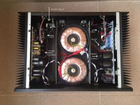
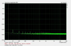
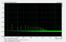
I did some noise measurement (bw 20k, amp input shorted) by sound card (direct input, no voltage divider)
Toroids were rotated so that the mains noise was the minimum in the left channel.
Toroids were rotated so that the mains noise was the minimum in the left channel.
Attachments
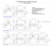
what does "K200Mv3 K6v1" tell us?
The best diy non-gnfb amp you can get for few bucks 😀

K200Mv3 - HEC amp
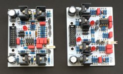
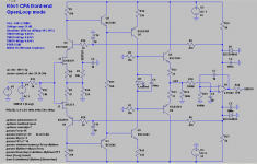
K6v1,K6v2 are CFA frontends
K6v2 - HEC amp
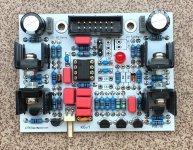
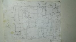
K6v1 - see attached pictures, currently v2 is configured as open loop and v1 as local NFB
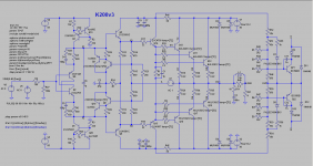
I'm working on bjt version of K200v3 which has better parameters than mosfet
Attachments

Hi LKA, interesting project you have going!
So far we didn't hear much from you how the different IPS and OPS combinations sounds like, are you going to reveal any information in the near future? 🙂
So far we didn't hear much from you how the different IPS and OPS combinations sounds like, are you going to reveal any information in the near future? 🙂
Hi LKA, interesting project you have going!
So far we didn't hear much from you how the different IPS and OPS combinations sounds like, are you going to reveal any information in the near future? 🙂
Unfortunately, I can't hear the difference. Even open loop configuration ( frontend and also buffer) sounds me good. Maybe it's due to low power level ( 1-5W, openloop thd 0.0x%) at which I listen to music. Maybe there are another reasons, I don't know, perhaps my hearing is not adequate.
new bipolar version from ltspice
Attachments
Do you want to share the pcb?🙂
I am willing to share it for experienced builders only. Not easy to build, requires some level of skill. Send me PM if you think you are 😉


HEC is such a neat concept. It greatly improves the transition through the low non-linear Gm at current crossover for class AB. This is much more pronounced with mosfets. The higher the bandwidth of the error amplifier and driver, the more accurate the correction will be.😊 I bias vertical FETs at around 20 to 30mA and see no crossover at full load. The error signal is quite fast, and at very low volumes, the error signal is even larger in magnitude than the output. 
Also I find that bootstrapping HEC and driver circuit works fabulously and eliminates the higher tier voltage supply.
PS: If you use very fast devices, high ft, for error amp and drivers, dont forget base and collector stopper resistors. 😉
Also I find that bootstrapping HEC and driver circuit works fabulously and eliminates the higher tier voltage supply.
PS: If you use very fast devices, high ft, for error amp and drivers, dont forget base and collector stopper resistors. 😉
In a previous project when I had time🙄 I made a junk amp using scrap parts from the bin to see how good of an amp I could make using the worst type of output device, TIP100/105 Darlington....as to which type of device Hawsford EC was designed for. 😀 As I recall, it sounded surprisingly really nice.🙂
HERE
I did happen to find the output stage drawing that I used in a file.
* indicates heatsink mount, B and C connect to control logic for fault shut off.
I like your PCBs. One thing though, I have had issues with connectors in the past, have you experienced issues with loose or bad connections? I blew up outputs before because bad connection made logic control go haywire!
Attachments
Last edited:
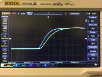
K200v3 bipolar version is finished. 10 transistors, 4 diodes and 2 resistors are mounted on the heatsink. you have to be very precise when drilling, mounting, soldering


I measured the buffer with signal generator and oscilloscope into resistive load 4R5.
blue trace - input signal
yellow trace - signal before output coil
1kHz clipping at 81.6Vpp
slew rate 125V/us (mosfet version 280V/us)
blue trace - input signal
yellow trace - signal before output coil
1kHz clipping at 81.6Vpp
slew rate 125V/us (mosfet version 280V/us)
Attachments


Is it underbiased?
Attachments
Last edited:
Is it underbiased?
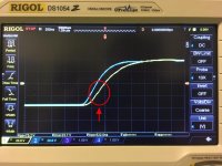
That little wrinkle is the moment the feedback loop lost track of the input signal that has a greater rate of transition than it can follow, and from that moment on the amp slewed.
That little wrinkle is the moment the feedback loop lost track of the input signal that has a greater rate of transition than it can follow, and from that moment on the amp slewed.
I doubt it is slew limiting. It still seems to follow a regular RC-time exponential curve rather than the straight line that is so characteristic of slew rate limiting. It never is the feedback loop that can't follow (after all that's just a resistive divider) but the amp output itself. Due to limited charging current for the compensation cap(s).
BTW LKA very nice board. Extremely well done.
Jan
Last edited:
I doubt it is slew limiting. It still seems to follow a regular RC-time exponential curve rather than the straight line that is so characteristic of slew rate limiting. It never is the feedback loop that can't follow (after all that's just a resistive divider) but the amp output itself. Due to limited charging current for the compensation cap(s).
BTW LKA very nice board. Extremely well done.
Jan
we don't see the straight line all the way to the top because the input signal slowed down before long and the amp recovered from slewing as the input signal slowed down enough. There does seem to be a straight line portion, from roughly -15V to +5V on the rising edge of the output trace.
With that scope shot LKA was assessing his amp's slew rate according to his post. I'd guess he did have to get the amp to slew for at least a short moment in order to come up with the slew rate as he did.
I use the same method in assessing slew rate of my own amps. Drive with square wave, then loosen up the input R-C LPF just enough to see the wrinkle at about 1/4 of the way from the bottom of the rising edge. This wrinkle can be seen in simulations too, by the way.
I hear what you are doing but that's not a good test. You really have to drive it into full slew rate to measure it. The wrinkle can be anything; it could just be the transition through the crossover. There's no way to determine the actual slew rate from this shot.
The way to do it is driving into full slew rate and measuring on the straight line the time it takes from min to max, that's the voltage/time of slew rate.
You can't determine the slew rate from those shots because there is no slew rate limiting going on, nothing to be seen, just exponential RC risetime.
That you can determine from this shot.
Jan
Last edited:
Please find some useful info here: #172: Basics of Op Amp Gain Bandwidth Product and Slew Rate Limit
LZ yes that's a nice explanation!
I just had a car ride and thought about it some more.
There are two other ways to determine whether your amp is SR limited. You can probe the amp input (after the RC input filter) and compare to the output. In the scope shots shown above you will see that the two curves will be basically the same - the amp is nicely in it's linear range and not SR limited. If you decrease the input RC product (or remove it) you will get a square wave at the input and see straight line edges at the output indicating SR limiting.
The other method is to probe the two input diff pair inputs and subtract them, so you get the effective input signal. In the linear range it will be a very low level signal, essentially the error signal that drives the amp.
But when SR limited you will start to see very high peaks on that diff signal. The amp output falls behind and the output is missing part of the wave, which gets divided down by the feedback divider and subtracted from the input giving the huge spikes.
But this method is not easy in practice due to the sensitivity of the inputs for scope probe capacitances. But it's a great method in simulation.
Jan
- Home
- Amplifiers
- Solid State
- HEC amp