Looking at the graphs again its not too chaotic on the back, quite orderly to eye where wavelength is long in comparison to box size. There seems to be only few main features sticking out and roughly explained by features I touched on previous posts, which makes another nugget of information: sound interacts strongly with the first few corners/faces of the box but after that point intensity is so much reduced there is no effects seen. Basically sound goes around corners (diffraction) but not much of it comes around the box anymore, in other words sound bubble keeps on propagating outward from the box. Basically from features on the (simulated) single driver graphs its possible to estimate size of transducer, baffle size, baffle edge radius or lack of, then box depth and edge radius at the back, size of the back (panel).
I have not done trigonometry on these one but guestimating it looks about to match the reasoning. Here is image showing the features identified in previous posts. If it feels crazy talk to you then please comment 😀
I have not done trigonometry on these one but guestimating it looks about to match the reasoning. Here is image showing the features identified in previous posts. If it feels crazy talk to you then please comment 😀
Attachments
Last edited:
My summary thinking about "normal" boxed speaker with drivers on the front panel, in small rooms (home environment):
-low freq will go around the speaker, box 3D shape contributes to dispersion details (below baffle step, gradually) and eventually meet front/side walls and get reflected, making more interferences. Speaker placement in the room has great effect to sound, deep and quite wide peaks and nulls happen. Wide baffle shifts BSC lower and minimizes bad effects in very important midbass.
-mid freq (500-2kHz) is mostly affected by baffle dimensions and edge contour making diffractions (narrow peaks and dips in response), but energy radiated to wide angles and backwards is small, irrelevant. Mid-tweeter crossover is very important to smoothen transition from mid to tweeter. Early reflections from floor and sidewalls can have great influence on response in the room and at the spot, speaker positioning and angulation is important.
-high freq (2-3kHz-) gets interferences from very small discontinuities of the baffle surface and edges. Dispersion is quite narrow, so placement of the speaker has minimal effect to sound.
Basically this has been known at least for decades, but perhaps not understood and appreciated by all designers and consumers making choices... Now Klippel NFS measurements by Erin and Amir have opened the eyes for many more people
Widish baffle 3-way

Small bookself 2-way

-low freq will go around the speaker, box 3D shape contributes to dispersion details (below baffle step, gradually) and eventually meet front/side walls and get reflected, making more interferences. Speaker placement in the room has great effect to sound, deep and quite wide peaks and nulls happen. Wide baffle shifts BSC lower and minimizes bad effects in very important midbass.
-mid freq (500-2kHz) is mostly affected by baffle dimensions and edge contour making diffractions (narrow peaks and dips in response), but energy radiated to wide angles and backwards is small, irrelevant. Mid-tweeter crossover is very important to smoothen transition from mid to tweeter. Early reflections from floor and sidewalls can have great influence on response in the room and at the spot, speaker positioning and angulation is important.
-high freq (2-3kHz-) gets interferences from very small discontinuities of the baffle surface and edges. Dispersion is quite narrow, so placement of the speaker has minimal effect to sound.
Basically this has been known at least for decades, but perhaps not understood and appreciated by all designers and consumers making choices... Now Klippel NFS measurements by Erin and Amir have opened the eyes for many more people
Widish baffle 3-way
Small bookself 2-way

These two measurements show the same trend from relative cabinet dimensions. The Linton 85 is 300 x 330 only slightly deeper than it is wide and there is a single null around 150 degrees dominating the low end pattern.Widish baffle 3-way
This one is 180x250 so relatively deeper than it is wide and the two null split pattern is slightly more obvious.Small bookself 2-way
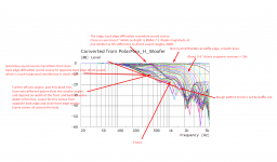
The main diffraction hump which you term the ridge is at about 430Hz 440Hz which corresponds very closely to the full round trip dimensions of the cabinet which is 80cm. This trend is repeated in the deeper cabinet but it's more spread out due to the bigger ratio of dimensions.I have not done trigonometry on these one but guestimating it looks about to match the reasoning. Here is image showing the features identified in previous posts. If it feels crazy talk to you then please comment 😀
Any time there is bunching of traces, or further off axis angles are louder than smaller there is diffraction.
The null formations are obvious, the Sd of the driver is higher than a 5 to 6", this was the same Sd as a piston to represent Vineeth's Satori woofers WO24P, in the simulation it is a diameter of 170mm.
Yeah its very interesting to compare the graphs and try to reason the features of speakers.
The Linton Juhazi attached shows the polar pattern, which changes less with frequency than with the 12.1. Linton has the blue null region extend down to ~500Hz where it is almost 135deg supercardioidish range. The 12.1. the blue line extends only to about 800Hz or so, indicating width of the box is less, roughly half perhaps, not as much path length difference around each side of the box. Could also include effects the height is less but this is simplified reasoning so its just guestimate.
With all the info we can try and reason how to extend the cardioidish response down in frequency. Simplest thing would be just double up Linton dimensions, widths and depths and all, to get it to 250Hz but if transducers are kept the same their surroundings change and performance would change some as well. Pattern would still change from supercardioidish to cardioidish as frequency rises though. If one wanted to keep the blue line flat through frequency range, at 135deg or 150deg or 180deg, which ever, then the path length difference would have to vary with wavelength to keep it constantly ~1/2wl at certain observation angle. In other words box size would need to vary with wavelength and its not possible. The blue line(s) is always sloping in these graphs because box size is static.
Last edited:
Basically yes to off-axis angles up to where observation point gets diffraction generated "back wave", which is in opposite phase, the ridge forms. Greater off-axis angles behind the box that see the opposing back edge have mostly direct sound coming from both (all) sides of the box and get more boost, "secondary sound" is now louder and in phase, in comparison, and makes stronger interference pattern. Kind of a fold happens in the response, far off-axis response is affected by louder and in opposite phase secondary sound than few degrees before, illustration attached.Any time there is bunching of traces, or further off axis angles are louder than smaller there is diffraction.

edit.
There was far off-axis angle drawing in the previous post attachment and here is few more trying to illustrate the "fold" in response, same side back edge diffraction contribution to the response starts to diminish while opposite side back edge starts to increase as observation angle increases.

Illustration is missing third drawing showing situation directly behind the box, but its easy to imagine. Observed directly from back side 180degrees, path length around both sides of the box is same and SPL is quite strong directly behind the speaker for wavelengths that diffract around the speaker to back side in the first place.
Last edited:
To make "the fold" feature in response reduce, to bring responses via both back edges more similar to each other to any direction one could combine the back edges into one, aka pointy back, triangular enclosure. Make the back edge rounded to reduce diffraction related secondary sound source and also the ridge reduces in magnitude, especially on-axis. This would smoothen the response radically to all directions, and also make the response more omni, less of a nulls form anywhere as path length difference through each side could be shorter than baffle width, which means not much short wavelength sound radiates to backside to make any destructive interference, it would be mostly constructive interference, hense more omni like pattern. Or make the enclosure a sphere, similar effect.
Last edited:
Quick overview on delays associated.
Delays for the back edge diffraction related secondary sound source would be roughly 2x box depth. There is much talk about making early reflections similar to direct sound in order to reduce their effect to perceived sound quality. For example vertical early reflections would happen in smallish /typical living room roughly at ~2-3ms for floor reflection and ~5ms for ceiling reflection. 90cm driver and listening height, 2.5m room height, 2-3m listening distance.
20cm deep box would have ~40cm / ~1.2ms delay associated with back edge diffraction generated secondary sound source, depending on toe-in and listening angle.
30cm deep box, 60cm, ~1.8ms
40cm deep box, 80cm, ~2,3ms
50cm deep box, 100cm, ~2,9ms
Reasoning from concern about audibility of early reflections that fall <5ms after direct sound the back edge diffraction might also be audible, especially since its frequency response is very different than direct sound consisting mostly wavelengths on the baffle step. Reasoning from this it would be reasonable try to minimize the back edge diffraction amplitude by rounding the back out, by removing the edge.
So, simplifying we can deduct that if one is concerned about audibility of this back edge diffraction then it would make sense to round of back corners of the box with quite significant round radius, for about all typical box sizes.
About typical box sizes: assuming hearing system would integrated delayed sound with direct sound if it arrives <1ms then box depth should be < 0.5ms, ~17cm. Or, making it have similar delay as ceiling reflection for example, to 5ms, would make box depth of about 80cm.
Last edited:
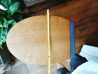
Interesting and thought provoking thread! Question: my boxes are elliptical in cross-section, with flat baffle of course. Actual depth is 42cm, width 33cm.
So basically no rear diffraction coming from sharp edges. But what effects to expect in polar responses i am asking my self?
I am planning polar measurements in two weeks, once the D.C. errors in my measurement setups is delt with ( floor and ceiling reflection reduction will be with absorbtion plates (basotect etc)). What 3lse to take into account to get clearing measurements?
Would be nice to add these to the results shown in this thread.
Cool 🙂 if at all possible try at least double reflection free window time from typical living room measurement setup of ~4ms to something like 10ms in order to get some kind of resolution for low mids <1kHz to see the effects. It might be better to make ground plane measurements outside to really get some resolution. Or do some BEM simulations.
If its oval shaped enclosure, which is basically unfied back edges into one, then I would speculate response be more alike to ideal case than with sharp and separate back edges as in examples recently in this thread with "the ridge and fold". Ideal response, with no back edges, can be obtained with VituixCAD diffraction tool as it shows only the baffle edge diffraction.
edit. and thinking more it probably does not matter as you already have done what you can for it, rounding the back out. If you do get some measured results then it wold be cool if you posted them.
Last edited:
hmm, the fold would appear, as it is reduced sound to side because its ~direct sound (and perhaps back edge diffraction). When angle increases enough sound from both sides sum up and we get boost, max boost 180deg as sound around both (all) sides interfere constructively.
edit. Yes, I think fold can be reduced by reduce amplitude to increasing angle so that there is not much to sum right on the back, from either side. Conversely, not reducing would make more like supercardioidish, also depth of the box would affect but thats more local effect with not as wide bandwidth. Just thinkin out loud, perhaps something I did not see in fluids graphs while he did.
edit. Yes, I think fold can be reduced by reduce amplitude to increasing angle so that there is not much to sum right on the back, from either side. Conversely, not reducing would make more like supercardioidish, also depth of the box would affect but thats more local effect with not as wide bandwidth. Just thinkin out loud, perhaps something I did not see in fluids graphs while he did.
Last edited:
If you can get long enough window for the impulse responses to have resolution on low wavelengths. I speculate you might see something like this would happen in comparison to fluid simulated rectangular box response.

That seems likely, for Jan most of the effects being discussed before were predominantly for the low mid woofer range where the baffle step is. Directivity effects for mid drivers are still there but at a reduced level as the drivers are becoming more directional. The felt is tricky to simulate the effect of and felt varies so much in how it behaves. The shape you made have will have smoother directivity and less directivity.I speculate you might see something like this would happen in comparison to fluid simulated rectangular box response.
Yes, the felt is tricky. I tried to simulate in the difftaction tool of Vituixcad the topical bump, dip, bump effect . I neede to increase the width ofcthe baffle from 26 to 36cm to get a simulation that looked like the measured on axis response. Do not know if this is a correct simulation, nor the cause of this difference, but the measurements will be done again but better. Hopefully leads to better understanding.
wow... i am just catching up. Thanks for all the info!
I have been in the weeds and now see what I missed with my Z baffle test: motor noise and the delay it adds. I forgot to mention I am pushing a little $40 tweeter beyond manufacturer specs. The decay is in the head shadow and the 8" has a better decay so my ear will hear whatever driver is best. This is how I see it as ok.
waterfall of z baffle 3"vs15"vs30" at 1m


motor noise is always there. It is a complex mix of motor noise + baffle + 2pi/4pi and everything else in the room + unknown unknowns. Making the baffle short can mess with the time and add anti-resonances. It also seems like if your 4pi wobbles your 2pi will too.
The GD is showing how time is messed up:


Again, thanx for all the posts.. now i need to read 'em.
it is cool to see heat instead of sound... this is in zero gravity

I have been in the weeds and now see what I missed with my Z baffle test: motor noise and the delay it adds. I forgot to mention I am pushing a little $40 tweeter beyond manufacturer specs. The decay is in the head shadow and the 8" has a better decay so my ear will hear whatever driver is best. This is how I see it as ok.
waterfall of z baffle 3"vs15"vs30" at 1m
motor noise is always there. It is a complex mix of motor noise + baffle + 2pi/4pi and everything else in the room + unknown unknowns. Making the baffle short can mess with the time and add anti-resonances. It also seems like if your 4pi wobbles your 2pi will too.
The GD is showing how time is messed up:
Again, thanx for all the posts.. now i need to read 'em.
it is cool to see heat instead of sound... this is in zero gravity
Here is the top view of my speaker, the black grille is 3cm deep inside. I want to get a smooth as possible curved shape from M and T driver transition into the edge, thus removing sharp edge and its diffraction effects.
That is a cool shape.
A smooth edge creates nulls in a criss-cross-like mesh in the decay. Smooth things are like a disco ball for decay. The slow motor decay will push this all into the power. On my rounded speaker, every axis measured with a diff. wobble. You can see why in the decay. So a round thing can be harder to make flat at some frequencies.
If you have DSP, running the minimal baffle is the only way to get the on and off-axis the same-ish. Round is a second but does extend the decay time and disco-ball it.


Waveguides seem like they are made if you do not care about the decay and want power. This seems like passive speaker tech since DSP can boost things.
...
I hope to have hifijim over for a listen next week. It is a Be dome on a baffle vs cheap dome and no baffle shootout. Both with XO's between 1-2khz. One cares about vertical directivity more than the other. I still need to get them in the final spots and level matched.

The day after I shot this the baffle on the left came apart after a year of being held together by tape. I did learn along the way that all drivers, even on foam, should use some screws. I did not "patch' my first speaker with this info. So I got to wake up seeing drivers hanging by wires.
Since the speaker came apart I thought of showing how it works in a vid. I was thinking how the surface acts like a spring for some freq. and then it dawned on me that tapping could bring this out in the opposite way.
So I hope to see if making any size change to a baffle is worth it by adding a small anti-FS baffle to the small tweeter.
This is a quick mockup in green .I need to work on how I place them in a circle. All of my swatches put them in square patterns.

The baffle will have 8 small chambers that are 10mm deep. I might make a deeper one since the baffle can be long.
Last edited:
The pictures of the decay patterns, at what distance does it apparently go 'circular' ? Just me trying to understand what these pictures are telling me ;-)That is a cool shape.
A smooth edge creates nulls in a criss-cross-like mesh in the decay. Smooth things are like a disco ball for decay. The slow motor decay will push this all into the power. On my rounded speaker, every axis measured with a diff. wobble. You can see why in the decay. So a round thing can be harder to make flat at some frequencies.
If you have DSP, running the minimal baffle is the only way to get the on and off-axis the same-ish. Round is a second but does extend the decay time and disco-ball it.
View attachment 1092871View attachment 1092872
Waveguides seem like they are made if you do not care about the decay and want power. This seems like passive speaker tech since DSP can boost things.
...
I
It is born that way. A point source makes circles. An infinite baffle makes 1/2 circles. So the choice is a matter of moving in either of those directions. For the real tweeter, frequencies below 2khz shoot behind the tweeter. (i have only measured 1 time). The 2d sim was for 800hz.The pictures of the decay patterns, at what distance does it apparently go 'circular' ? Just me trying to understand what these pictures are telling me ;-)
At what point does the decay change from hot mess to nice? I hope to find that out. The current tweeter is 40mm wide. A 68mm and 100mm are on deck.
..
I just measured some parts I had before I got a DATS3 and a new part.
The BlieSMa t25b and ETON 3-212 have not been measured before. The tweeters are a matched pair and the ETON's are not. Could have fooled me!


The audax Mg is the monkey wrench tweeter. This is the top-of-the-line Audax tweeter (unless you go for gold). I just purchased the one to compare to the others. It has a big plate that I really want to get rid of.


all the data:

Dang! hifijim's dance card is all filled out. I misread an email. I will have to wait for his thoughts. Well, more time to level match. My bass needs some TLC.
..


My hatches are battened down. (The drivers are screwed in.) Don't rely on friction and tape! Not for a year anyways. The baffle is still not glued. I'm not done testing ideas for the perforations.
I have prob said this before, but I dig just the metal. I would like to have no plastic or animal fiber in the current project if possible- inside and out.
..
My hatches are battened down. (The drivers are screwed in.) Don't rely on friction and tape! Not for a year anyways. The baffle is still not glued. I'm not done testing ideas for the perforations.
I have prob said this before, but I dig just the metal. I would like to have no plastic or animal fiber in the current project if possible- inside and out.
- Home
- Loudspeakers
- Multi-Way
- Headshake's far field 3way