First, thanks @hifijim , @fluid, @tmuikku , and @Juhazi for adding ideas and pointers to this thread. It really helps me find my way.
...
The desktop t25b + eton "ideal driver" sims:
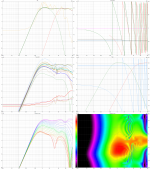
500mm c-to-c with the tweeter on a stick
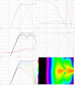
second-order XO using the existing baffle
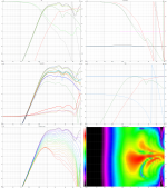
first order using the existing baffle.
...
To see what was possible, the first step was to just see a 1st order slope on each driver and do a rough polar: This is 0-45 degrees for each driver.
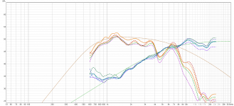
The dotted curves are out of the sim. The solid lines are the average of all of the measurements with a 500ms gate. Each dashed line is a 4ms gate of each axis measurement.
After a bunch of messing around on-axis, i checked the off-axis around 75-85 degree with the first order:
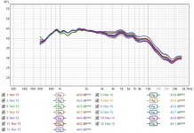
This is me eq'ing it more (prob too much)
1st order timing:
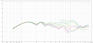
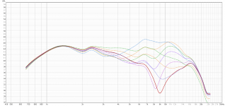
This is me running through each timing delay that the fusion amps can do. It was very close to the ideal sim.
The second order was much easier to set up. I had to do very little to make it work.
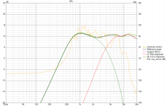
2nd order sim vs raw measurement of the eton. I tried to make the eton dip the same amount in the XO as it does naturally.
...
The desktop t25b + eton "ideal driver" sims:

500mm c-to-c with the tweeter on a stick

second-order XO using the existing baffle

first order using the existing baffle.
...
To see what was possible, the first step was to just see a 1st order slope on each driver and do a rough polar: This is 0-45 degrees for each driver.

The dotted curves are out of the sim. The solid lines are the average of all of the measurements with a 500ms gate. Each dashed line is a 4ms gate of each axis measurement.
After a bunch of messing around on-axis, i checked the off-axis around 75-85 degree with the first order:

This is me eq'ing it more (prob too much)
1st order timing:


This is me running through each timing delay that the fusion amps can do. It was very close to the ideal sim.
The second order was much easier to set up. I had to do very little to make it work.

2nd order sim vs raw measurement of the eton. I tried to make the eton dip the same amount in the XO as it does naturally.
A few weeks ago I messed with the visaton dsm50 a bit. The top plate that has the grill was removed and I measured it a few ways. I also took it apart and messed with the internal foam.

DSM50 and a tillandsia pruinosa.
I measured without the grill at 1m w/ and w/o the felt teeth.
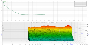
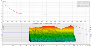
GD:
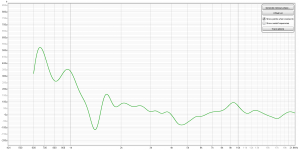
The next test was with the dsm50 pointed up on melamine. The mic was above it. This was to allow me to swap the foam inside the dsm50's magnet without moving things too much. The mic was closer than 1m.
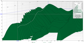
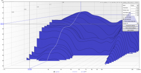
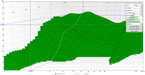
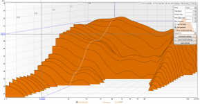
The foam that comes with the dsm50 seems to add just the right resistance to balance things out- it still distorts but it is fast and flat. I am tempted to stick some perforated discs inside just to see what happens.
Another view without the internal foam:
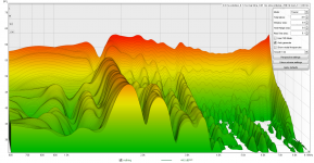

DSM50 and a tillandsia pruinosa.
I measured without the grill at 1m w/ and w/o the felt teeth.


GD:

The next test was with the dsm50 pointed up on melamine. The mic was above it. This was to allow me to swap the foam inside the dsm50's magnet without moving things too much. The mic was closer than 1m.


The foam that comes with the dsm50 seems to add just the right resistance to balance things out- it still distorts but it is fast and flat. I am tempted to stick some perforated discs inside just to see what happens.
Another view without the internal foam:

Last edited:
tldr: i measured a rough polar of two XO's using sister tweeters off the same mid. Also, felt can't zap diffraction humps.
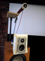
I was wondering if I could measure from one spot and see some of the mess from both baffles. I picked 1m from the middle space between both. This spot is off-axis for both but is the XO spot for the 500mm baffle. So it is not apples to apples. But the mid is the same mid and the mic is at the same position for each axis measurement. I must have used a bit of boost on the one XO so it was louder on accident.

Two 2nd order XO's. The mic was calibrated for the lower set. The top is the 44mm edge radius baffle and the bottom set is the 500mm tweeter on a stick. The each have their own XO's so I expected some differences. Looks like I still have some baffle step.
I measured at 1m from the top tweeter and used a wood block to move around on-axis at the same distance.
Notice on the bottom set, the tweeter on a stick, it has the hump of extra power on axis that @fluid modeled centered at 6680hz.
The top set of graphs is the baffle with an edge radius + baffled tweeter. I am guessing the dips off-axis are caused by the need for an inverted XO. For sure the 10khz fade is caused by the felt shape. I will strip down the baffle to see.
As a last experiment, I slapped a bunch of different felt shapes on the tweeter on a stick to see what can happen. It is a monkey paw for diffraction. All diffraction dips get larger off-axis with felt. So using a 68mm tweeter might just at the edge of too big to have no baffle.
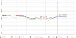
This is showing the on and off-axis for the tweeter with diff. felt shapes. Solid is on axis, dotted is off. Blue is with nothing - notice it has the flattest off-axis. As the amount of felt increases, the sides can be cleaned up but the main hump only gets larger. My quick solution is just to eq down a bit and skip all felt for the tweeter on a stick for now.

I was wondering if I could measure from one spot and see some of the mess from both baffles. I picked 1m from the middle space between both. This spot is off-axis for both but is the XO spot for the 500mm baffle. So it is not apples to apples. But the mid is the same mid and the mic is at the same position for each axis measurement. I must have used a bit of boost on the one XO so it was louder on accident.

Two 2nd order XO's. The mic was calibrated for the lower set. The top is the 44mm edge radius baffle and the bottom set is the 500mm tweeter on a stick. The each have their own XO's so I expected some differences. Looks like I still have some baffle step.
I measured at 1m from the top tweeter and used a wood block to move around on-axis at the same distance.
Notice on the bottom set, the tweeter on a stick, it has the hump of extra power on axis that @fluid modeled centered at 6680hz.
The top set of graphs is the baffle with an edge radius + baffled tweeter. I am guessing the dips off-axis are caused by the need for an inverted XO. For sure the 10khz fade is caused by the felt shape. I will strip down the baffle to see.
As a last experiment, I slapped a bunch of different felt shapes on the tweeter on a stick to see what can happen. It is a monkey paw for diffraction. All diffraction dips get larger off-axis with felt. So using a 68mm tweeter might just at the edge of too big to have no baffle.

This is showing the on and off-axis for the tweeter with diff. felt shapes. Solid is on axis, dotted is off. Blue is with nothing - notice it has the flattest off-axis. As the amount of felt increases, the sides can be cleaned up but the main hump only gets larger. My quick solution is just to eq down a bit and skip all felt for the tweeter on a stick for now.
Last edited:
If you want the cleanest response without diffraction you need to manage the exit of the wave from the driver over whatever baffle there is and off the edge as smoothly as possible. Discontinuities like the extra felt sections in front are not going to help in that goal. They can be used to spread or shape diffraction but not to avoid it. To do that the felt would have to be quite absorptive which these measurements show it is not.
I have thought about this over the last week or so. I remember suggesting a higher (3k) crossover point for a couple of reasons. One, you seem particularly sensitive to distortion effects in the lower treble range, so I thought a higher crossover point would potentially help with that. I also suspected that a 3k crossover would lead to a better DI curve given the size of the Eton mid and the very close spacing to the Bliesma tweeter. This was all intuitive judgment calls on my part... no analysis to back it up.He's been telling me to XO at 3000hz many times with the t25b.
I am pleased has worked out well !
j.
Thanks, fluid!If you want the cleanest response without diffraction you need to manage the exit of the wave from the driver over whatever baffle there is and off the edge as smoothly as possible. Discontinuities like the extra felt sections in front are not going to help in that goal. They can be used to spread or shape diffraction but not to avoid it. To do that the felt would have to be quite absorptive which these measurements show it is not.
I do wonder if there are better felt shapes that involve more air space instead of solid shapes. But like you said, they wont fix it.
Well, thanks again for pointing in that direction. It motivated me to explore things with a clean slate.I have thought about this over the last week or so. I remember suggesting a higher (3k) crossover point for a couple of reasons. One, you seem particularly sensitive to distortion effects in the lower treble range, so I thought a higher crossover point would potentially help with that. I also suspected that a 3k crossover would lead to a better DI curve given the size of the Eton mid and the very close spacing to the Bliesma tweeter. This was all intuitive judgment calls on my part... no analysis to back it up.
I am pleased has worked out well !
j.
But I do think the original XO is good for some music. Just not Freddie Mercury and bongos.
I hope to get your opinion of a 1st order vs 2nd order vs 6th order and a baffle vs no baffle mono session. I'll send an email.
...
Speaking of the ETON just reminded me I had a GD measurement from center of the baffle at 1m and 4ms gate. This is just the 3-212 with no EQ.
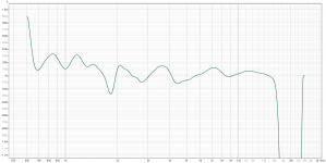
The ETON 3-212 has a little issue at 1.8khz with the box I am using.
That will depend on how accurately the phase can be measured. An inherently flat microphone and measurement setup that does not really need compensation is helpful as not all calibration offsets allow for phase to be considered.I wonder what the precision and accuracy of group delay measurements are with the sound cards and microphones we use?
There will need to be no reflections and the time of flight delay will need to be removed.
Is that normal group delay, or excess group delay?
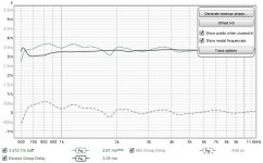
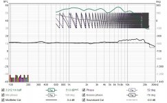
Eton 3-212 gd + spl 1m center of baffle
I think what you are calling normal is the minimun group delay in REW.
I use a loopback and have a sound card calibration along with the mic calibration. That measurement in the previous post was rounded to roughly 1/6th + gated to 4ms + I let REW estimate the 0 from the measurement using the loopback.
https://www.roomeqwizard.com/help/help_en-GB/html/graph_groupdelay.htmlThe group delay for the measurement is calculated from the slope of the phase trace... The group delay will include any delay in the measurement due to time delays in the PC or soundcard, processing delays in the equipment and delays due to the time sound takes to travel from source to microphone. Delays in the PC or soundcard can be eliminated by using the Use loopback as timing reference
I am going to attempt a tiny perforated baffle + felt on the t25b in the hope of zapping the baffle diffraction.
This doc is from the perforated metal engineer's handbook or some name like that. I have the doc on another machine. The doc was freely posted on the internet. The nomogram is about finding the center number- the open area of the surface. I messed with the pink lines for my previous battle and the target frequencies were darn close. But a roughly 1cm chamber really just messed with the decay. Now I want to increase the back chamber size in the hope that it can reduce some of the power on axis.
1.2mm is the smallest hole i can have cut with the service I use. So the left column is locked. The number there is based on the effective throat size. See the description in the doc and the dark line is the example for it. I will attempt the green line for my first go. If I go larger than 1" I need a plate that breaks the nomogram if I stick with the hole size. My fingers are crossed that this will be enough. Either way, it will be neat to see what happens.
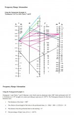
Ok, so the nomogram says that if I want to roughly target 5500hz, I need a roughly 34% open area with the 2cm back chamber. With the 1.2mm holes, the next step is to calculate the spacing to arrive at 34% open area:

I am still working on the part but now know how big it should be and the spacing.
This doc is from the perforated metal engineer's handbook or some name like that. I have the doc on another machine. The doc was freely posted on the internet. The nomogram is about finding the center number- the open area of the surface. I messed with the pink lines for my previous battle and the target frequencies were darn close. But a roughly 1cm chamber really just messed with the decay. Now I want to increase the back chamber size in the hope that it can reduce some of the power on axis.
1.2mm is the smallest hole i can have cut with the service I use. So the left column is locked. The number there is based on the effective throat size. See the description in the doc and the dark line is the example for it. I will attempt the green line for my first go. If I go larger than 1" I need a plate that breaks the nomogram if I stick with the hole size. My fingers are crossed that this will be enough. Either way, it will be neat to see what happens.

Ok, so the nomogram says that if I want to roughly target 5500hz, I need a roughly 34% open area with the 2cm back chamber. With the 1.2mm holes, the next step is to calculate the spacing to arrive at 34% open area:

I am still working on the part but now know how big it should be and the spacing.
My kung fu for making round perforated shapes was no good. I was using larger grids and just removing dots manually. After some youtube watching and using the pattern brush, things are faster. It is nice to increase the size of a circle by a fraction of a mm and watch all the dots fall in line.

I might try two baffles: One that uses the t25b as a wall and one that does not. The most complex part is the top steel plate- It will cost $25USD each to make. The rest of the layers I have not quoted but should be much cheaper since they are wood.
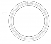
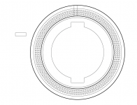
rwo versions of a 43% open area plate. The inner dark line is the outside of the t25b.
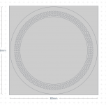
quoted 304 SS shape.
There is still more to do.

I might try two baffles: One that uses the t25b as a wall and one that does not. The most complex part is the top steel plate- It will cost $25USD each to make. The rest of the layers I have not quoted but should be much cheaper since they are wood.


rwo versions of a 43% open area plate. The inner dark line is the outside of the t25b.

quoted 304 SS shape.
There is still more to do.
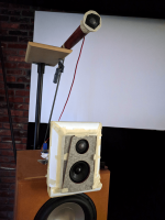
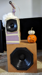
Had hifijim over for a listening session. We compared the left to the right. We also compared a LCR dolby digital track on the 3 jbl 580 horns vs mono on the two 3ways. Lastly, we compared a 2nd order on the baffle t25b and the no baffle t25b.
Thanks again, @hifijim for doing the drive and lending your time!
(Note:There were no pumpkins for the listening session. )
Some of the music we zipped through:
Last edited:
It was an interesting listening session. When I saw the left side, with its very large C-to-C distance between the Eton 3" mid and the Bliesma tweeter-on-a-stick, I was expecting to hear some audible artifacts of the very large CTC... the crossover is at 3k (yes?) so this is a CTC of 3 or 4 x wavelength.
Instead it seemed well integrated, and I could not hear the tweeter as a separate driver. This completely went against my expectation.
Both left side system and right side system had a very nice sense of space. Right side was wider and more forward, left side was taller but with more depth.
On some tracts of music, I preferred the right side, on others the left. The left side had a slightly different tonal balance, a slightly recessed upper midrange / lower treble, so for me, this drove whether I would prefer it on any given tract. It was program dependent.
I will leave it to Headshake to describe his impressions, and to describe the technical details of exactly what goes into the left side and right side systems.
j.
It was an odd session, right? The last time it was very easy to pick one side over another. With a new XO and a change in the spacing, it is much harder. The right side is the same as last time.It was an interesting listening session. When I saw the left side, with its very large C-to-C distance between the Eton 3" mid and the Bliesma tweeter-on-a-stick, I was expecting to hear some audible artifacts of the very large CTC... the crossover is at 3k (yes?) so this is a CTC of 3 or 4 x wavelength.
Instead it seemed well integrated, and I could not hear the tweeter as a separate driver. This completely went against my expectation.
Both left side system and right side system had a very nice sense of space. Right side was wider and more forward, left side was taller but with more depth.
On some tracts of music, I preferred the right side, on others the left. The left side had a slightly different tonal balance, a slightly recessed upper midrange / lower treble, so for me, this drove whether I would prefer it on any given tract. It was program dependent.
I will leave it to Headshake to describe his impressions, and to describe the technical details of exactly what goes into the left side and right side systems.
j.
The XO on the left side is around 3600hz.
left side ideal sim and right side ideal sim - just look 1khz on up since these are just mid-tweeter sims. I use these for the XO and a general idea of the timing.
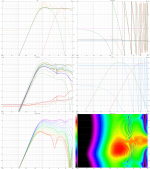
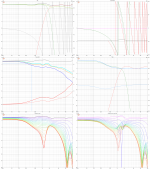
Both in reality are a little tighter than this going off-axis.
I was interested in hearing a driver play alone where another has an XO. I think I prefer the logic of one driver, one job. Having 2 drivers play where ears are sensitive is interesting but can be a little muddy. This can also make it comfortable too. Audio is such a mess of compromises.
Thanks again, @hifijim ! I am excited to hear your next speaker! I promise to have things in stereo for the next session.
...
https://www.researchgate.net/public...Properties_of_Finely_Perforated_Wooden_Panels
I found a paper on perforated wood. Some neat graphs from it:
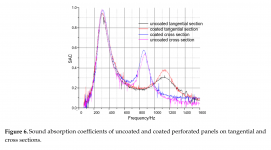
Coating the baffle/perforated surface
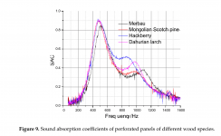
I need to check the density of these. If the top line is the densest then I should be best off with metal.
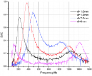
magenta is a nonperforated baffle. This is comparing diff. hole sizes.
The investigation confirmed the following three findings: Firstly, by taking panel vibration intoconsideration, the Maa-Flex model revealed better accuracy in absorption predictions as compared withthe Maa-MPP model. Secondly, both perforation Helmholtz resonance absorption and panel vibrationeffects occur simultaneously, and the effect of eigenmode vibration can increase the absorption peakvalues and widen the absorption bands, while the absorption induced from panel mass spring vibrationcan occur independently. However, wood’s porous structure has little impact on the absorptionproperties. Thirdly, the panel mass spring vibration was affected by the dynamic mechanical properties.With increasing damping factor, the peak amplitudes for mass-spring vibration absorption went down.With increasing dynamic Young’s modulus, the absorption peaks induced from mass spring vibrationshifted towards higher frequencies.
Last edited:
Perorations in the wild: the TB Speaker and SBA mids.
audioxpress has a review of both:
https://audioxpress.com/article/tes...me-midrange-from-the-sb-acoustics-satori-line
https://audioxpress.com/article/test-bench-tb-speaker-75-1558sh-high-end-home-audio-3-dome-midrange
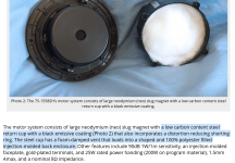

These drivers both have great decays. It is neat to see all of the different things at play. @hifijim was just suggesting to use rubber for the rear chamber and look- the md60n has a damping pad. The perforated wood paper also says to use something other than a hard surface. I will try a few materials in the t25b baffle's chamber floor.
The visaton dsm50 has an empty plastic chamber behind the mid. The yamaha JA0801 has a metal box. We've come so far!/s
Yandex can translate images. I used it on the ja0801 spec sheet I could never read.
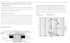
I used the 2d image to show what the JA0801 would look like with a chamber similar to the new mids.
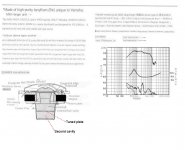
The hole size is like the Q of a filter. Now I just need to stop buying drivers that give me no access to the back chamber.
audioxpress has a review of both:
https://audioxpress.com/article/tes...me-midrange-from-the-sb-acoustics-satori-line
https://audioxpress.com/article/test-bench-tb-speaker-75-1558sh-high-end-home-audio-3-dome-midrange


These drivers both have great decays. It is neat to see all of the different things at play. @hifijim was just suggesting to use rubber for the rear chamber and look- the md60n has a damping pad. The perforated wood paper also says to use something other than a hard surface. I will try a few materials in the t25b baffle's chamber floor.
The visaton dsm50 has an empty plastic chamber behind the mid. The yamaha JA0801 has a metal box. We've come so far!/s
Yandex can translate images. I used it on the ja0801 spec sheet I could never read.

I used the 2d image to show what the JA0801 would look like with a chamber similar to the new mids.

The hole size is like the Q of a filter. Now I just need to stop buying drivers that give me no access to the back chamber.
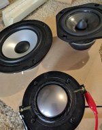
Audax am100z0, Visaton Al130m(made in germany), and a visaton dsm50.
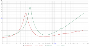
imp of the cone mids. Whatever one has the best 500hz to 1500hz moves on to the next round. I just made some PE box + foam baffles to measure this week.
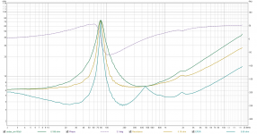
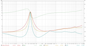
EPDR is a combined phase and imp to show what the amp sees if I understand it.
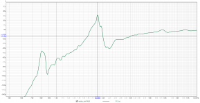
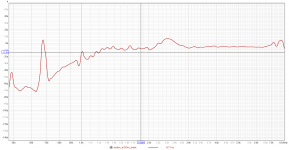
GD is derived from the phase of an impedance sweep.
Next up is a log sweep to see what happens at 1m and with a little box.
visaton al130m (5" mid)
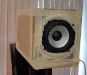
A pink foam baffle and the second smallest PE box. I have it on a speaker stand that is prob messing some of the measurements. The stand is on a table to get things off the floor. The box has a single layer of 1" melamine foam inches from the back wall of the box. The space behind the melamine has stuffing.
The measurements were done at 1m for the al130m. The ja0801 was closer if I recall.
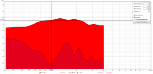
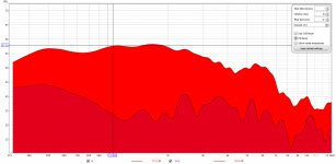
I thought the ja0801 had a nice 1khz decay until I saw the visaton mid. The ja0801 was measured on a larger baffle and with a driver I returned due to being broken. So add a big asterisk to the ja0801 measurements. I do think it is neat to see it for reference.
There are two al130m decays here. One graph has a 44mm edge radius at the top and one side of the baffle and another graph has no edge radius. the 44mm edge seems to make 2khz worse on-axis.
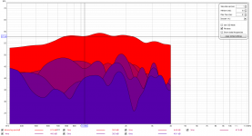
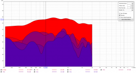
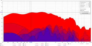

A pink foam baffle and the second smallest PE box. I have it on a speaker stand that is prob messing some of the measurements. The stand is on a table to get things off the floor. The box has a single layer of 1" melamine foam inches from the back wall of the box. The space behind the melamine has stuffing.
The measurements were done at 1m for the al130m. The ja0801 was closer if I recall.


I thought the ja0801 had a nice 1khz decay until I saw the visaton mid. The ja0801 was measured on a larger baffle and with a driver I returned due to being broken. So add a big asterisk to the ja0801 measurements. I do think it is neat to see it for reference.
There are two al130m decays here. One graph has a 44mm edge radius at the top and one side of the baffle and another graph has no edge radius. the 44mm edge seems to make 2khz worse on-axis.


Last edited:
Hey! Flush mounting will for sure improve things. This was just rounding at the top and one side (i need to cut the rest). I will do a 44mm rounding on all sidesThe driver is not flush mounted. So you will have a influence. Surprised that the on axis with without 44mm rounding shows so little difference.
Some time distortion on a dome, 3",4",5", and 8" drivers. The 3" was taken at the center of the baffle and is only a 600hz on up sweep the rest start lower. The dome mid was less than 1m. I remeasured the larger PE box for the ph2460. My new trick is to put tape on the driver and use a laser to measure from the mic to the tape. I used the laser before but diff materials have diff. emissivities so the tape keeps things the same. So the 4",5", and 8" were measured this way.
The visaton al130m and the am100z0 both sounded nice w/o eq. I can see why now in the GD. A flat line is a perfect behavior and the al130m does it with a little delay and only in a small range. The power dips are lost in this graph so next will be to eq the al130m and measure that.
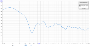
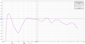
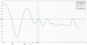
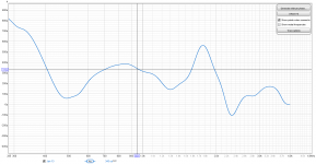
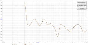
The visaton al130m and the am100z0 both sounded nice w/o eq. I can see why now in the GD. A flat line is a perfect behavior and the al130m does it with a little delay and only in a small range. The power dips are lost in this graph so next will be to eq the al130m and measure that.


- Home
- Loudspeakers
- Multi-Way
- Headshake's far field 3way