OK, I just check the amp with the new BIAS. I have around 80 mA and the offset is stable (7mVolt). After 15 minutes temperature is 75~80º while I use my Sennheiser HD600 (300 Ohm) if you turn up the volume, temperature increases and can exceed 80 ° (without cover)
With Dt990 (600 Ohm) you need turn up the volume more... and the temperature slashing 90 ° at 5 minutes so I turned off immediately the amp.
DB139/140 has a max operation temperature of 150º but the PCB and the other components (regulation caps, Fet, resistors) are experiencing very high temperatures (60~65º)
I don´t feel at ease knowing this.
Really, I've only heard a slight improvement with high impedance headphones. A little more dynamic and better control of the bass with less volumen but this is something very relative because I've only heard five minutes
The original pcb not serve for this mod. You need a big heatsink like the Damon 🙁🙁

+150C=Ultra Hi-END.
 😀😀😀
😀😀😀

150°C ,maybe I give it a try with my old unit😀
I have to do just a few measurements and "fine tuning", then I will post some pictures of my new amp. (provided that I find out how to get pics in the post😕)
I have to do just a few measurements and "fine tuning", then I will post some pictures of my new amp. (provided that I find out how to get pics in the post😕)
Last edited:
150°C ,maybe I give it a try with my old unit😀
I have to do just a few measurements and "fine tuning", then I will post some pictures of my new amp. (provided that I find out how to get pics in the post😕)
🙂🙂🙂
Attachments


Thanks a lot damon for the step by step advice, exactly the right one for a internet-dummy like me!🙂🙂
I kind of figured there's not much more to tweak with this PCB. I've started on a design using different parts, jfet's instead of BC550C/bc560c, one channel per board, off-board PS etc.
I might even send the design to a PCB house in the future. Too many other builds with higher priority...and it's expensive, not only the PCB's but also getting matched jfet's.
I might even send the design to a PCB house in the future. Too many other builds with higher priority...and it's expensive, not only the PCB's but also getting matched jfet's.
If I design a new pcb, probably I would use a separate PSU and a large PCB for amp (with off-board Mosfet for example) but I wouldn't change the basic components.
Well, I figured a dual mono design is better in some ways.
The choise to use jfet's is simply that I like the sound from the k170/j74.
I'm not a big fan of large PCB's tbh.
The choise to use jfet's is simply that I like the sound from the k170/j74.
I'm not a big fan of large PCB's tbh.
For check different caps types or using a individual heat sink like a Beta 22 for example, you need some space.
Yes, I like the k170/j74 but they are very expensive and I don´t know if worth using it here.
Yes, I like the k170/j74 but they are very expensive and I don´t know if worth using it here.
OK, I'd ended with LBCL. BIAS 150 mA, bias of drivers 6,25 mA, DCout 0,6 mV and 2 mV. T in closed box after 4 hours +51C. 🙂
Next amp will be for STAX ESL. 🙂
Next amp will be for STAX ESL. 🙂
Last edited:
150mA - you lucky boy.
Very nice low offset, I assume it keeps stable due to thermal coupling - well done🙂
Very nice low offset, I assume it keeps stable due to thermal coupling - well done🙂
150mA - you lucky boy.
Very nice low offset, I assume it keeps stable due to thermal coupling - well done🙂
I decided that 175 mA a little more.🙂
175mA... god!
Is the difference significant in relation to normal BIAS? I mean at the sound obviously
Is the difference significant in relation to normal BIAS? I mean at the sound obviously
175mA... god!
Is the difference significant in relation to normal BIAS? I mean at the sound obviously
150 mA vs. 175 mA - not difference.🙂
I think 100-140 mA enough.🙂
175 mA for me - not scary. My small Hiraga's 20W AMP have bias 1,3A. 😉
Last edited:
Hi,
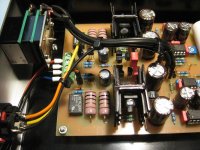
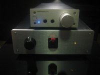
Some pictures of my just finished redesigned BCL? The only thing which remained unchanged is the output buffer, every thing else is very different.
Please be tolerant regarding my home etched PCBs (single layer), they dont´t look that nice and of course you can´t compare them with manufactured PCBs.😱
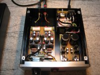
1st pic.: you can see that my enclosure is slightly larger than the original.
2nd. pic: I divided the project into 2 PCBs, PSU and amp , the transformer is a toroidal 15VA and mounted in a séparée
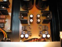
3rd pic.: PSU caps Mlytic 6800µF/63V, for the voltage regulation I adapted the marvellous Jung/Didden superregulator to my needs ( I hope Jan won´t bite my head off therefore)
4th pic.: coupling caps Mundorf Mcap 3.3µF -> AD797 gain stage +10dB -> volume pot. 10k TKD CP2500 -> LM4562 unity gain follower (I can hear you damon - "very crappy opamps"😉🙂) this arrangement gives a noise improvement of 14dB (source impedance 200R, gain +10dB, volume -6dB) compared to the orig.
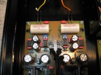
5th pic.: output buffer, complementary transistors thermally coupled - BD139/140 as well as BC550/560, DC offset remains stable ,right <1.5mV ,left <1mV
output relays, including delayed startup an DC protection
The layout is designed consequently dual mono, so I wasted some parts ( e.g. relay, LM4562).
The result is an excellent crosstalk figure of -102dB (200R source) at 10kHz, my orig. BCL measures about -75dB.
I think it´s enough for the moment, maybe tomorrow I will add some more details.🙂
Some pictures of my just finished redesigned BCL? The only thing which remained unchanged is the output buffer, every thing else is very different.
Please be tolerant regarding my home etched PCBs (single layer), they dont´t look that nice and of course you can´t compare them with manufactured PCBs.😱
1st pic.: you can see that my enclosure is slightly larger than the original.
2nd. pic: I divided the project into 2 PCBs, PSU and amp , the transformer is a toroidal 15VA and mounted in a séparée
3rd pic.: PSU caps Mlytic 6800µF/63V, for the voltage regulation I adapted the marvellous Jung/Didden superregulator to my needs ( I hope Jan won´t bite my head off therefore)
4th pic.: coupling caps Mundorf Mcap 3.3µF -> AD797 gain stage +10dB -> volume pot. 10k TKD CP2500 -> LM4562 unity gain follower (I can hear you damon - "very crappy opamps"😉🙂) this arrangement gives a noise improvement of 14dB (source impedance 200R, gain +10dB, volume -6dB) compared to the orig.
5th pic.: output buffer, complementary transistors thermally coupled - BD139/140 as well as BC550/560, DC offset remains stable ,right <1.5mV ,left <1mV
output relays, including delayed startup an DC protection
The layout is designed consequently dual mono, so I wasted some parts ( e.g. relay, LM4562).
The result is an excellent crosstalk figure of -102dB (200R source) at 10kHz, my orig. BCL measures about -75dB.
I think it´s enough for the moment, maybe tomorrow I will add some more details.🙂
Attachments
Last edited:
150mA - you lucky boy.
Very nice low offset, I assume it keeps stable due to thermal coupling - well done🙂
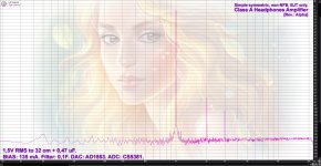
Old Alpha version.🙂
(As I remember here was little mistake, I'd used 1 uF cap on load instead 0,47uF).🙁
Attachments
Hi,
Some pictures of my just finished redesigned BCL? The only thing which remained unchanged is the output buffer, every thing else is very different.
Please be tolerant regarding my home etched PCBs (single layer), they dont´t look that nice and of course you can´t compare them with manufactured PCBs.😱
1st pic.: you can see that my enclosure is slightly larger than the original.
2nd. pic: I divided the project into 2 PCBs, PSU and amp , the transformer is a toroidal 15VA and mounted in a séparée
3rd pic.: PSU caps Mlytic 6800µF/63V, for the voltage regulation I adapted the marvellous Jung/Didden superregulator to my needs ( I hope Jan won´t bite my head off therefore)
4th pic.: coupling caps Mundorf Mcap 3.3µF -> AD797 gain stage +10dB -> volume pot. 10k TKD CP2500 -> LM4562 unity gain follower (I can hear you damon - "very crappy opamps"😉🙂) this arrangement gives a noise improvement of 14dB (source impedance 200R, gain +10dB, volume -6dB) compared to the orig.
5th pic.: output buffer, complementary transistors thermally coupled - BD139/140 as well as BC550/560, DC offset remains stable ,right <1.5mV ,left <1mV
output relays, including delayed startup an DC protection
The layout is designed consequently dual mono, so I wasted some parts ( e.g. relay, LM4562).
The result is an excellent crosstalk figure of -102dB (200R source) at 10kHz, my orig. BCL measures about -75dB.
I think it´s enough for the moment, maybe tomorrow I will add some more details.🙂
good looks, but I have some stupid questions.

 😀
😀Thanks, I will answer every question (except the right lottery numbers for next week).🙂good looks, but I have some stupid questions.
Thank you blackdod.🙂Andreas your "clone" is on other level. Very nice
Well, during soldering the PCBs I recognised things I would do different in my next attempt, also I used only a low number of "boutique parts", so there is still potential for further improvements. But for the moment I shouldn´t be too obsessed.
I would like to say a few words about the sound.
I directly compared my own build with the Lehmann (same sound levels of course), it´s a matter of a few seconds to replug the amps.
I must admit that my amp is a big step forward (not the right place for modesty😉), it`s easy to recognise a clear difference.
The sound is much more open, plenty of "air" between the instruments. Mainly with classical tracks I can really "feel" the recording location, with the Lehmann I can´t experience this.
But I should stop with the self-laudation now and be just happy about the result.🙂
- Home
- Amplifiers
- Headphone Systems
- [Headamp] upgrading a Lehmann BCL clone