I like the idea challenging and fun but unnecessary to compete without completing the thing 🤓
For today I cannot contribute due to some private chaos but as soon I could check the datasheet of the mentioned 2sc/2sa types I try to make my mind about the stages.
The drawn discrete solutions are more than intriguing to give this phono-pre a try!
Surely we need to do some economic thoughts else we got something that might does a perfectly fine job but noone is able to bring it alive.
One suggestion is also to use the nice red WIMA caps, never let me down!
If my wife is not watching I think about a small CNC for milling PCBs
Somehow the sparemoney needs to be burnt!
Chestnutspread aka "Kastanienaufstrich" is a french abomination made for loosing teeth and getting early heart issues - but gosh it's tasty!
Gladly not every supermarket got it listed else I run into serious trouble!

My beloved diary,
Something very strange has happened. When we entered Haudegen's apartment after the long overnight drive from Capri, or was it Athens, I must have been bitten by a mosquito.
I fell into a psychedelic dream - flying white sausages in lederhosen chased me. A black hole swallows me up, out the back again and I run over mountains of Leberkäse, try to hide in the Obatzda, drown in wheat beer ... We play master and servant - the CEO is mean to me. Another stitch! I fall into a strange sleep - sometimes I play with the other kids, but Bob is stupid. He likes to show off, wants to be a great builder to please the others. They all fall for him, especially the big one. He's in charge here (he thinks) and I have to do what he asks. They once took away my toys just because my bridge was much more colorful than Bob's. He's now an architect and a tattletale ...
At some point I woke up from this confusion and looked around - it's a strange room, no windows, no doors, apparently everything here consists of soft mattresses. I can't move my arms. How did I get into this jacket?
A few months later I was allowed to go to the open ward, what luck, everything is so colorful here - and we are allowed to play with plasticine, everyone gets their own "Smarties" every day. It's called therapy, what nonsense!
I heard from a fellow patient that "Haudegen" had run off with the lady of the house. He now runs a very successful consultancy firm (for all things audio). They live in a pretty house on a lake with orange trees.
Sometimes they play cricket in the garden.
You stick with me, my diary - the head nurse says to me: "Prof. Dr. Dr. Aduert Reutler asks you to come to his room (he is the new head of the department). I'm terrified, another CEO like that, my lord.
And so ends
our accompanying story for now.
HBt.
@Chestnutspread,
I might be able to make a suggestion at the weekend, we'll see. But I think your suggested twist is great. We should push ahead with the project now, provided our other commitments allow it. Otherwise, fire free. Anyone can work here, it doesn't bother me, on the contrary.
🙂
Last edited:
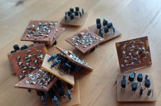
Five transistor OP-Amp.
The module could look like the photo. This topology works perfectly, but it is also not unknown. I particularly like the interchangeability, among other things the input differential amplifier can also be built with two jFets. Calculating the six ohmic resistors is child's play, you quickly have a basis with which you can do a lot. Optimizations for special applications ...
In one of my amplifiers, the jFet variant can be found in two stages as a complete preamp, with the famous LM3886 working as the output stage - I wanted to test this concept and wow.
Enough chatter!
The challenge is +80dB open loop gain, otherwise the EQ has to be set up in two stages - and anyone can do that.
Or the really hard trip follows and we have to correct the time constants, thank God our fathers and mothers left us tables for this.
"Lieber Kastanienbrotaustrich",
I would have absolutely nothing against the two of us putting your idea into practice. The Haudegen thread can rest in peace. Why don't you start a new thread? It could be called "MM-EQ: the discrete and economical approach" and from now on it would be the collection point for development and concrete implementation.
A link in this thread (here) would finally close the chain and represent the starting point.
Greetings
HBt.
Psst.
I'm already all jittery.
Attachments

By the way:
+/-5V to +/-18V as supply voltage range!?
You can also play around with this and explore the sweet spot in terms of the best sound. Of course, you can also do this in terms of measurement.
Not everyone has the measuring equipment, but an FFT will do, who still works with a selective level meter today?
That's a good idea, we had fun with the storyline and as mentioned before a fun project ended in something totally different serious that should be followed!
I would be in the boat and see what can be done and do some experiments.
The PCB CNC is probably more necessary than I initially thought! 🤓👌
I would be in the boat and see what can be done and do some experiments.
The PCB CNC is probably more necessary than I initially thought! 🤓👌
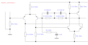
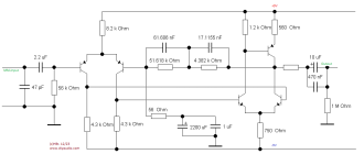
As a working basis, I suggest the following nomenclature among Europeans, see picture.
I start a first simulation with:
RE1 =8k6
RC1, RC2 = 4k3
RE2 = 3k1
RC3 = 1k2
(RC4), RE3 = 560
+/- 9Vdc
I won't explain my further procedure (the actual work and art) in detail - this isn't a workshop or anything else.
I start a first simulation with:
RE1 =8k6
RC1, RC2 = 4k3
RE2 = 3k1
RC3 = 1k2
(RC4), RE3 = 560
+/- 9Vdc
I won't explain my further procedure (the actual work and art) in detail - this isn't a workshop or anything else.
Attachments
First results:
Vuo >= 90dB
fog >= 20kHz
rao
high impedance, which was to be expected, but is not a problem for the time being. Currently > 17kOhm (don't be alarmed, this is normal in this case).
RE1 change to 8k2 and RE2 to 750 Ohm.
Just a simulation and first impression ...
Vuo >= 90dB
fog >= 20kHz
rao
high impedance, which was to be expected, but is not a problem for the time being. Currently > 17kOhm (don't be alarmed, this is normal in this case).
RE1 change to 8k2 and RE2 to 750 Ohm.
Just a simulation and first impression ...
Madness,
this is a pleasure. It works straight away. However, the time constants can still be corrected a little (computationally and metrologically, simulatively ...).
Here is my starting aid, this throw still has limitations - but what the heck.

this is a pleasure. It works straight away. However, the time constants can still be corrected a little (computationally and metrologically, simulatively ...).
Here is my starting aid, this throw still has limitations - but what the heck.
Attachments
But now I want to relax and observe the further development -> don't consume, always these boring ready-made products ... Here we go now!
Bye,
HBt.
Bye,
HBt.
I can hardly keep still
Please consider what a negative feedback loop does, or what a negative feedback loop basically is.
The network presented is nothing more than a complex resistance of two resistors that feed a fraction of the output back to the input.
The dimensioning rule (cooking recipe) only applies if an ideal amplifier with a differential point is present. Its input resistance is infinitely large, its output resistance infinitely small, its slew rate enormous (and thus also its bandwidth), of course its (open loop) gain must be huge (infinite).
And that is precisely what is not the case in our example.
ra is quite large, re is actually quite ok and still low, Vuo is sufficiently large for our purpose at just under 31623.
Now the closed loop comes into play and we have a control loop, we know the principle of the vanishing input variable - apparently automatically the input resistance increases dynamically and the output resistance decreases.
Unfortunately -
our coupling factor is not linear, it is frequency-dependent because our negative feedback network (Rn forms a divider, a four-pole) is complex.
our ra (also re) is now frequency-dependent and not constant; between 500Hz and 2k1221, ra is 50 ohms (roughly speaking).
Below this it increases linearly, above it decreases linearly - theoretically.
That's why I think it's great that you want to take on the challenge, the old school way.
Our fathers and great-grandfathers mastered this problem, even with just two, sometimes three transistors or two triode tubes.
With integrated operational amplifiers, anyone can do it nowadays and if you plant the RIAA network passively between two linear stages, it's even really easy.
Dear Chestnutspread,
please move forward on the rocky road, there is much to explore and learn.
Do you have an oscilloscope and a good sine wave generator, maybe even both analog? A multimeter and good ears?
We can hopefully ignore possible noise for the time being, first we need a basis and the necessary understanding of the control system.
You could also start with the basic circuits with bipolar transistors, but pulling a discrete OP out of the hat right away is quite daring.
Do you have any specialist knowledge? I don't suppose you're a bricklayer by trade.
Kind regards,
HBt.
(you can count on my help and support)
I got an apprenticeship as an electrician with a focus more on electronics but too late to know the technics of the pioneers.
My background in the end is the sum of mere interest in audio and always being curious.
Due to not living alone anymore I don't have "real" measurement equipment anymore.
I need to rely on some cheap digital helpers eg DATS for signals but could also use Audacity of course.
The oscilloscope was a victim of a wet storage room that nearly killed all my stuff.
But this joyride starts on a simulation base and depending of the outcome and availabilities of the parts I do think about getting the PCBs done or even better doing 'em myself.
If there is interest we can do a group buy and see what happens.
This project is a joyride and alot can be found in books or even from the parts manufacturers themselves eg linear systems.
I'm still in process of checking which parts are best suited for the application and are still available.
Somehow I realized I probably need to give up the TO90 body type and except some three/six legged SMD as the LS844.
I'm on the hunt to find something comparable to the OOP LS170 - there must be more than only this little guy.
For the moment it's more about checking datasheets - a huge pile of non-standardized datasheets!
Deeply immersed in the simulation
I specify
no abnormalities, deviations from the RIAA playback curve in the range between 30Hz and 15kHz less than +/- 0.15dB.
The rolloff of the inevitably occurring fourth time constant is just under 200kHz, which is completely unproblematic. If we want to correct this, we add a 1kOhm and 1nF low-pass filter at the end.
The dynamic input resistance is around 47k,
so everything is already in order. I'm confident that we'll get a handy little EQ up and running - I can do the real measurements.
Maybe the insurance will cover some of your domestic damage, water is a real problem these days (with the dramatic change in climate) ... A multimeter would be great for the restart.
All the best
for you and your family,
HBt.
(lets exchange contact data via pm, if you like)
Then I'll draw a circuit diagram and check the possible noise behavior - my Christmas present.
What name should the EQ have, something mythological perhaps?
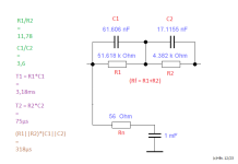
R1 = 51k1 plus 511 Ohm
R2 = 4k3 plus 82 Ohm
C1 = (100nF plus 150nF) || 1n5F
C2 = (33nF plus 33nF) || (470pF till 560pF)
plus means in series!
What name should the EQ have, something mythological perhaps?
R1 = 51k1 plus 511 Ohm
R2 = 4k3 plus 82 Ohm
C1 = (100nF plus 150nF) || 1n5F
C2 = (33nF plus 33nF) || (470pF till 560pF)
plus means in series!
The output noise power in the entire audio range drops (RIAA-typical) from 10^-11 to 10^-15 [V^2/Hz]. At full scale - we can therefore expect an acceptable SNR for MM.
A test setup could start now, but don't forget the blocking capacitors and 4700µF support capacitors.
BC550 & BC560 type C should also work well.
The optimum can be found later, also the best and lowest noise transistors as well as an adapted dimensioning of the resistors.
Have fun with it - everyone is welcome to try it out here and post their results and thoughts. Santa clauses (may) step forward ..!
HBt.
Psst
I can already (make mistakes)
😉
Attachments
We already know the gain and the RIAA network. We want to do the entire phono pre in a discrete way. For the moment I'm checking the possibilities we got on hand with dual-jfets. Direct thermally coupled pairs with a high possibility to have minimal tolerances.
Somehow I'm already stuck with the ls844...
...but you are right - starting with the bc550/560s on a breadboard should do the trick for proof of concept.
Somehow I'm already stuck with the ls844...
...but you are right - starting with the bc550/560s on a breadboard should do the trick for proof of concept.
By tomorrow I make my mind about the actual schematic and we should do the split from the original split due to various changes in the initial approach.
Maybe I'm not sounding enthusiasticly but I have pretty much fun on my side of the screen.
Thanks for teasing my brain cells 🙂
Maybe I'm not sounding enthusiasticly but I have pretty much fun on my side of the screen.
Thanks for teasing my brain cells 🙂
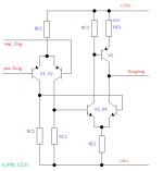
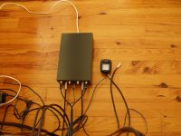
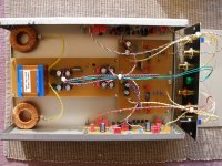
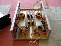
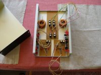
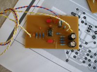
In all my archive and computer chaos, I can't find what I'm looking for. But I stumbled across the plans for my last PEARL 1, the original pearl ... here you can see, among other things, a simple and clever parallel regulator for the power supply ... here is it +/-12Vdc ..! But you can clearly recognize the principle and can use 9.1V Z-diodes.
(The original comes from an NAD-PP2 from 2005)
(The original comes from an NAD-PP2 from 2005)
Attachments
Last edited:
I'm a bit tired right now, but there was something about FETs or bipolar transistors at the input of MM preamps. At the moment I can't figure it out, we could ask Marcel van de Gevel (he's also active on this board) or search for his articles and papers. There was once something ...
If I understand you correctly, you would also consider a differential amplifier with jFets as your first choice.
This can be done, and is often used in consumer devices, but followed by an operational amplifier - and that's not stupid at all.
The simulations of the last suggestion #94 look really good, it's simply worth a try. I could send you my SPICE file, but you can quickly enter it yourself.
Cool,
it's coming along - all we really need is a layout with the components of our choice - and off we go.
If only I didn't already have 1001 equalizers, what should I do?
Bye,
HBt.
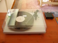
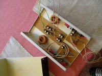
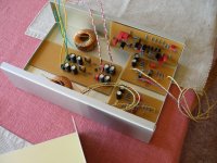
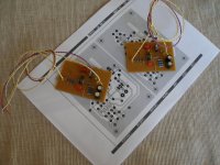
From the photo album of the little Haudegen,
a pearl.
Note from the narrator:
A real handicraft (not the final version) work by our hero,
(look) with this funny record player from the ninth Musical Fidelity CEO (from Vienna).
a pearl.
Note from the narrator:
A real handicraft (not the final version) work by our hero,
(look) with this funny record player from the ninth Musical Fidelity CEO (from Vienna).
Attachments
-
 Quelle.JPG133.2 KB · Views: 100
 -
 iPearl9.JPG163 KB · Views: 92
 -
 iPearl8.JPG201.1 KB · Views: 97
 -
 iPearl7.JPG173.7 KB · Views: 93
 -
 iPearl6.JPG181.3 KB · Views: 93
 -
 iPearl5.JPG177.5 KB · Views: 92
 -
 iPearl4.JPG181.2 KB · Views: 95
 -
 iPearl3.JPG161.6 KB · Views: 89
 -
 iPearl2.JPG160.1 KB · Views: 95
 -
 iPearl1.JPG160.7 KB · Views: 99
My god, if you look for something, you might find it eventually:
Between 2010 and 2017, I had an intensive long-distance exchange with a good friend, during which time countless ideas flitted through our heads, followed by just as many analyses ... and that at my age.
Of course, the RIAA approximation can also be implemented as a PID controller. This is not a new idea and it did not come from me, in 1990 I saw it in an application note.
Somehow the idea never left me (and now it appears in a parallel thread...). I didn't want to simply copy an AN and so the equalizer "Minimalistik" saw the light of day 25 years later. With battery supply to avoid any interference ... a really great sound, everyone immediately falls in love with this little equalizer ...
For me, this is first and foremost the "RIAA integrator" par excellence.
Greetings,
HBt.
Attachments

- Home
- Source & Line
- Analogue Source
- "Haudegen": MM-Phono-EQ