
Mark's posting #114 refers to the split riaa configuration shown as an example from my posting #113.
Now Mark adds R1 and R3 to 36.12kOhm and calculates the noise density to be 24[nV/sqrt(Hz)].
And that is quite simplified and ultimately not correct, which is what my posting #117 refers to. My posting #116 refers to the statement "and it has a gain at 1kHz of -20dB too" - and shows the solution to the 1/10 problem... Mark's posting #119 is nothing more than a red herring.
That's all
😉

VX 5021 P
"Klang und Ton 3/1996"
by THEL

There are endless examples in the archives of how you can or could implement an RIAA EQ.
This equalizer was a very popular DIY project in Germany for quite a long time, just like the Thomas Scheu turntable drive.
"Klang und Ton 3/1996"
by THEL
There are endless examples in the archives of how you can or could implement an RIAA EQ.
This equalizer was a very popular DIY project in Germany for quite a long time, just like the Thomas Scheu turntable drive.
That are your words:
@HRDSTL
In this thread you will find the correct dimensioning for the known passive RIAA decoupling networks.
But your approach is already extremely good, although I would have taken a different approach when choosing your first network. All in all, your equalizer "is not from bad parents", are you the author?
good luck,
HBt.
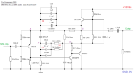
The best solution also sonically is to use passive corrections in 2 steps. It is also important to use high quality PP capacitors selected below 1%
I wanted to revive the sound of vinyl, I have some good pieces from 2000 to 2005, which are not available on stream and if they are, they are in poor quality. At the moment I only listen to tidal + dac. Many of the MM preamps published here also have RIAA correction in the feedback, which is not sonically optimal. I'm working on one preamp for MM, topology is from 90's but even then it was able to outperform several times more expensive preamps even from world manufacturers. There were also listening tests and this one outperformed literally all the participants. It was originally designed as follows: discrete input amplifier input pair 2sk170, + two stages of passive correction. In the original wiring were used NE5534, which nowadays is no longer any glory and so I needed to replace them with something better, the requirement was that the IO in THT design and with a maximum power supply up to 20V DC since behind the capacitive multiplier is about 19V. In the end I used the following types in the wiring (LT1028, LT1128, and in the DC servos LT1055, LT1012)
@HRDSTL
In this thread you will find the correct dimensioning for the known passive RIAA decoupling networks.
But your approach is already extremely good, although I would have taken a different approach when choosing your first network. All in all, your equalizer "is not from bad parents", are you the author?
good luck,
HBt.
Perhaps the time has now come to make the Haudegen project a reality. Our fallen hero Haudegen set out back then to put the pearls and ultra-sharp salads in the right light - and now an older design, the ACTIDAMP, suddenly appears on the surface ...

@HRDSTL
I assume that Haudegen's design (off the cuff) will be no worse than "actidamp", even without that well-known input thingy ...
@HRDSTL
I assume that Haudegen's design (off the cuff) will be no worse than "actidamp", even without that well-known input thingy ...
Who has the opportunity to build both, and nothing prevents you from comparing them in confidence. 🙂
Who has the opportunity to build both, and nothing prevents you from comparing them in confidence. 🙂
Please do not evade, but answer kindly the question I asked you - see OREAD. If you want to answer the why question there, please do so here in the Haudegen thread.
thx,
hbt.audio
"Basically, it should be noted that there is no concept that is per se superior to any other implementation."
As soon as we have digested this wisdom, we also realize how nonsensical @HRDSTL 's statement is. The only thing we all can do is to make (design)mistakes, more or less of them - intentionally or unintentionally!
It can almost always be assumed that the actions of Haudegen are intentional.
😉
kindly,
HBt.
If we want to split the RIAA-Network then we should use the correct method, please look at posting #113.
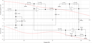
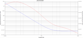
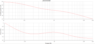
The pre-consonant in a new guise
A discrete circuit with incredible technical data:
RIAA deviation less than +/- 0.15dB and an incredible SNR of fabulous ..!
R(AB) corresponds to R1 of the network and is approx. 118kOhm, from which the missing values
R2=17k157
C1=18n56
C2=6n37
can be easily calculated.
r_out =50Ohm
r_in =47kOhm
This old 1970s EQ appeared in the equalizer thread
EXakt Mk2
in which @MartinX wants to link the consonant with the first stage of the design there.
kindly,
HBt.
Attachments
Retro, the wave of nostalgia
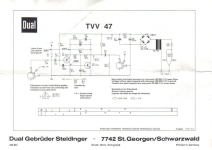
A look at the old dual hi-fi amplifiers shows us the standard circuit of the time with two NPN transistors - and this is where the fiddling with the time constants really starts, but +/- 0.3dB deviation from the RIAA standard is no problem at all. With a bit of effort and an impedance converter, a simple emitter follower at the output, we can approach +/- 0.15% again with a guarantee in the entire audio range. Normally, only 30Hz to 15kHz is given in the specifications anyway.
In the original, Dual set R2=82kOhm, C1=3.9nF and C2=1.2nF (even if R(AB) is in the order of 540kOhm). Without the EF at the output, the load must never be less than 150kOhm, never!
#
Will another candidate from the 1960s or 1970s emerge from obscurity? The Dual EQ is definitely not bad.
Attachments
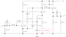
DUAL TVV 47 reboot

The appeal of the “old school”, with improved approximation to the RIAA recommendation - and without much fiddling around with matching capacitances -> 4n7 || 1nF and 1nF || 1nF -> FKP's.
Q1 = 2N2984
Q2 = BC177B
Q3 = BC109C
Q4 = BC109C
df = +/- 0.3dB
snr > 80dB
re = 47kOhm
ra < 100Ohm
C1a,b,c build-in subsonic with C3
(don't change the values)
A quick experiment!
HBt.
Attachments
- Home
- Source & Line
- Analogue Source
- "Haudegen": MM-Phono-EQ