"Haudegen": MM-Phono-EQ

Member
Joined 2020
Why not be bold again and simply reach into the component box?

No weeks of thinking, just have fun like a child. Just like in the old days, simply tinkering and listening to music. It's not quite that simple, because there's so much at the back of your mind ...

Design frame:
-Two-stage
-Voltage divider that bends back the cutting characteristic
-Gain about 40dB at signal frequency 1kHz
-One coupling capacitor at the input and one at the output
-Rebuildable, if it works
quite simple (KISS) and the hope that it doesn't noise - and above all works!

This problem has kept me up all night, being a 19 year old again. It's not easy to throw everything overboard and deliberately break some design rules.


Today:
I only listen via MCs, but if it works, I'll buy the nicest and cheapest MM my store has in stock.

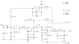
Here's my idea, the simulation results are perfectly fine - if I haven't made a stupid mistake.
You never know.

;)

Always be gentle,
HBt.
 

Attachments

  • Haudegen_MM.PNG
    Haudegen_MM.PNG
    3.8 KB · Views: 476
  • Like
Reactions: 1 user
Member
Joined 2020
I hope I don't sit down in the salad and get tomatoes thrown at me. The circuit is just a nightly mental exercise. Trumpeted out ...
 
Member
Joined 2020
And there it is - the lack of sleep:
The left coupling capacitor must correctly read 680nF not µ.

HBt.
("680µF ist auch für einen Haudegen zu viel")
 
Member
Joined 2020
Disclaimer

Any similarity with existing circuits or products is purely coincidental. But also not unlikely, because nobody is reinventing the wheel.
This circuit idea is freely available to everyone. Anyone is welcome to create their own layout and throw it on the scales.


HBt.
 
  • Like
Reactions: 1 user
Member
Joined 2001
are you sure the servo has the correct polarity? if you have a positive DC voltage output, will the noon-inverting servo feed an opposing polarity, appropriately scaled voltage to the non-inverting preamp's input to compensate?
 
  • Like
Reactions: 1 users
Member
Joined 2020
Sure in theory; without the servoloop' the output latchup to -Vcc. There is a mismatch at the Inputs of U1a, thats the inital cause. Look at the impedance ... Voltage offset (without servo) is round about -0,58...V at Pin 1.
 
Member
Joined 2020
:unsure:
Oh yes, it is a positive feedback ..! Must be blind :rolleyes:. Crasy, in simulation it works seemingly.
 
Last edited:
Member
Joined 2020
are you sure the servo has the correct polarity? if you have a positive DC voltage output, will the noon-inverting servo feed an opposing polarity, appropriately scaled voltage to the non-inverting preamp's input to compensate?
Thank you.

Urgendly, i need some sleep ... i was blind. Will check and fix it tomorrow.
 
Member
Joined 2023
This looks intriguing - maybe I need to stock up some components again and give it a try.

Do you plan to build this thing and do some measurements?
Would be interesting to see how well the simulation compares to the real world.
Unfortunately I'm not able to do this.

It's kind of funny to see a ne5532 and TL072 - these components are kind off getting forgotten and been replaced by topologies with JFETs.
No blaming here, just nice to see these coming up.
 
  • Like
Reactions: 1 user
Member
Joined 2020
Midnight in Germany,
the development department can't sleep. The customer overseas has tightened up the list of requirements even more:

No strain on the network
No automatic offset correction
No mechanical adjustment at the end customer, the buyer

He vehemently insists on as few components as possible (and as many as absolutely necessary) and unconditional DC coupling of the core.


The team is desperate, everything would be so easy if ...
The simulation says yes, but the well rested mind says no. "That tips".
 
Member
Joined 2020
Dear Chestnutspread,
please wait with this, of course a test setup is needed. So far it's still just a mind game, with a concrete background and an intention.

The choice of the two OPs is a very deliberate decision, including the 22kOhm (=10 times 2k2). Both are clearly different from each other (internally) - but above all they are not bad.

Single-ended circuits are generally easier to design than control circuits.
I'm really excited to see where the journey with the "Haudegen" project will take us all.

Everyone should feel called upon to lead Haudegen to success so that it lives up to its name.


Good night,
HBt.
(I'm impatient, just like I was when I was a teenager. Where is the breadboard? An idea & still quite innocent - that is the approach of the project. The joy of trying.)
 
Member
Joined 2020
@stocktrader200,
totally correct. That was "eine Schnapsidee", at the back of my mind was something other than only just the offset.


The juggling begins:

The first throw went completely wrong, totally unstable. But the team has fixated on a control loop - the client's attitude is slowly rubbing off and the circuit becomes complicated.

Let's hope nothing hisses.

A few adjustments here, a few there ... will the customer be satisfied with a TL074 and the label "HighEnd"?
A test setup is needed.


HBt.
(All comments, questions and suggestions are welcome.)
 

Attachments

  • Haudegen_MM_2.PNG
    Haudegen_MM_2.PNG
    4 KB · Views: 176
  • Like
Reactions: 1 user
Member
Joined 2020
In the meantime, we were able to appease the disgruntled customer. Our proposal is: one NE5532 and one TL074, both ICs are printed with a fantasy logo ... to give the impression of something special in the press.

That's one side of the story.


Now it's time to tinker and measure, maybe - a listening test.
 
Member
Joined 2020
Back from the lunch break

The development department shakes its head in unison.

CEO of our small consulting firm calls for a meeting. He is annoyed by the team's unwillingness to fulfill all the customer's wishes (and dreams).
Embarrassed faces. Everyone looks at their smartphones. The dinosaur of the team opens his mouth. Unfortunately, the boss doesn't like that. The PR department speaks up and announces: "we could get the customer's eye off a fancy MC transformer".

Employee Haudegen is sent back to the lab. Today, the team must at least present simulation results, and some sort of test circuit.

Suddenly!
19-year-old Haudegen wakes up from his nightmare. Has he seen the future?
 
Last edited:
  • Like
Reactions: 1 user
Member
Joined 2023
I like the topology of the output stage but not sure if I see a potential load or a kind of filtering that might be unnecessary.

The ongoing story went from funny bedtime story towards a more thriller-esque mood.
I would like to read a more gloomy film noir type - dinosaur disappears and the idea is sold in a shady back alley.
I'm not sure if I'm more intrigued by the phono or the presentation ;)
 
  • Like
Reactions: 1 users
Member
Joined 2020
Well, the second idea is not really good either.
No matter which idea you pursue, you can't implement a functioning servo with a TL071 core. The component is not good enough for this. It does not work dynamically in the case described. If you know the internal structure of the TL, this is immediately obvious. The suggestion works reasonably well, but it has serious effects on the frequency range below 100Hz. You can tweak the loop gain, but that won't help.
You have no choice but to use at least one more capacitor and set the DC amplification factor to 1.
Now the DC offset at pin 1 of the TL072 is almost -0.6V ...

And the circuit (theoretically) works perfectly. However, the strange push-pull output stage at the end must then be removed from the loop ...

HBt.
 

Attachments

  • Haudegen_MM_3.PNG
    Haudegen_MM_3.PNG
    2.7 KB · Views: 132
Member
Joined 2020
Dear Chestnutspread,

the simplest thing would be to make sure that the first OP (its input, the differential point) sees the same impedances.
A bootstrap might work. But you must not forget the noise.

The most reasonable would be a complete active equalization with only one NE5534.
Not only Douglas Self has shown us how this can be realized.

But again and again the passive divider comes into fashion or a partially active concept is preferred.
I question whether the additional output stage, the impedance converter, is really necessary.

HBt.


U1a = NE5532
U2a = TL072
 
Member
Joined 2020
The biggest wish is:

To feed the passive RIAA network with a source impedance of 0Ohm+/-j 0Ohm. And the following stage should have an infinitely large input resistance and no input capacitance (of course, otherwise nothing would be infinite). In other words, if you don't load it, then you don't have to fiddle with the values of the divider ...
And an approximation of +/- 0,1% to the desired curve is child's play - is always possible.
 
Top