How would I go about intepret this one? 😉
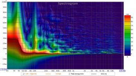
Learning by doing! (I know this is an SPL vs time, but what artefacts may account for this and that)
Learning by doing! (I know this is an SPL vs time, but what artefacts may account for this and that)
Attachments
Last edited:
Definitely something going on with the room near 38 and 105 Hz. Given the effects there are spread over time, I would say a room mode rather than a reflection arriving at the delay necessary to cause nulls at those frequencies. It looks different at/around 300 Hz where you also had an anomalous dip.
Room dimensions are 4,85W x 3,90D x 2,2H (m)
38hz 9m and 105hz = 3,25m
The room is concrete all around, with 2x2 framework (with 2" insulation) in front and 1 layer of plasterboard (1/2" thick) on all walls. Hardwood floor and naked concrete ceiling.
Absorption panels along walls, 2" thick with 2" of air behind them.
38hz 9m and 105hz = 3,25m
The room is concrete all around, with 2x2 framework (with 2" insulation) in front and 1 layer of plasterboard (1/2" thick) on all walls. Hardwood floor and naked concrete ceiling.
Absorption panels along walls, 2" thick with 2" of air behind them.
Room dimensions are 4,85W x 3,90D x 2,2H (m)
38hz 9m and 105hz = 3,25m
Raw dimensions do not consider windows, openings, squishy (or solid) walls, doors, etc. Those can move the findemental resonces.
dave
Concrete is good for room gain and bad for room modes. 2" of absorber spaced out 2" is good for perhaps 400 Hz and up.
You can use REW's room sim tab to see its prediction of the modes and the bass, for what that is worth. Of course one measurement is worth 1000 simulations but if you can find some correlation between sim and measurement you can save a lot of trial and error.
Of course the first thing to do is to cut those big LF peaks down with miniDSP PEQs
Of course the first thing to do is to cut those big LF peaks down with miniDSP PEQs
Those tools will be put to good use when the miniDSP2x4HD has arrived, but will try to sort things out as much as possible acousticly before treating the signal.
Thanks for adding to my thread, to all 🙂
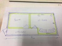
Here is a plan drawing of the area in my house.
Blue filled lines = concrete
Yellow lines = wood frame work/plaster board and insulation. These are kept thin without consideration of SPL attenuation 😉 There are no windows at all.
Pos 1-2-3-4 = a 4 seat couch / listening position
Hallway + HT-room listening area = 9m in width...38hz wave?
Blue filled lines = concrete
Yellow lines = wood frame work/plaster board and insulation. These are kept thin without consideration of SPL attenuation 😉 There are no windows at all.
Pos 1-2-3-4 = a 4 seat couch / listening position
Hallway + HT-room listening area = 9m in width...38hz wave?
Attachments
Last edited:
The asymmetrical placement of the arrays should give you some options to play with.
The 300 Hz is a reflection and should be dealt with in the room itself.
The 300 Hz is a reflection and should be dealt with in the room itself.
Did you install those slotted walls in the cavities? Any "w vs. w/o" measurements?
//
Are you thinking about the "Karlsonator aperature" I mentioned earlier? No, initial testing with the test chamber didnt give me confidence to continue with them. Not sure they are wrong, just felt adding those could give me more to deal with than I could chew.
The asymmetrical placement of the arrays should give you some options to play with.
The 300 Hz is a reflection and should be dealt with in the room itself.
I'll play a little with placement tonite, at the moment they are as close to the rear wall as possible. (front baffle approx 65-70cm out) The soffits prevent anything less due to the height of the arrays.
As far as room treatment goes, I have approx 1700l of soffit volume to use as bass traps, 20x30cm cross section.
Perhaps not for the 300hz drop but we'll see 🙂
Last edited:
Don't disturb the asymmetrical position 😉. There's a good chance there will be some differences between the left side and right side. You can actually use those differences to get a better sum overall. No need to shift positions for that, just look at what each array (separately) does best. You can use that (especially below ~80 Hz) to make them sum to a more ideal total. That's what you see in my summed result, that's also what I want to work on when adding the subs, to get each side that much better by itself.
The 300 Hz is a reflection messing with the response. It may/can come from any side, like wall behind listener etc. but can also be side wall... That should be fixable by finding the spot (usually the suspect is a mirror image of the array as seen from the listening area. If you place a mirror on each wall, do you see a reflection of one of the arrays there as seen from the listening area of interest? You see it in the filtered IR too as a peak after the main pulse.
The 300 Hz is a reflection messing with the response. It may/can come from any side, like wall behind listener etc. but can also be side wall... That should be fixable by finding the spot (usually the suspect is a mirror image of the array as seen from the listening area. If you place a mirror on each wall, do you see a reflection of one of the arrays there as seen from the listening area of interest? You see it in the filtered IR too as a peak after the main pulse.
Last edited:
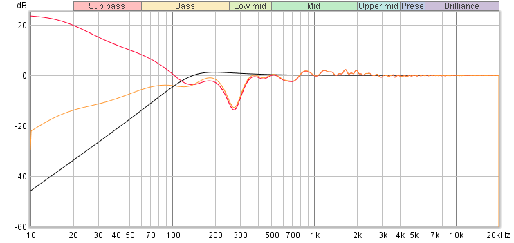
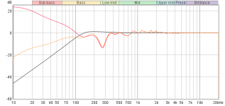
Was it the right array channel that had the close to 300Hz such out !!! below is a dirty quick model of trancducer position number twelve relative to floor using same 45 cm distance to rearwall and sidewall.
Black curve is 2nd order HP of 140,3Hz Q1 times red room curve results in orange curve.
Black curve is 2nd order HP of 140,3Hz Q1 times red room curve results in orange curve.
Attachments
Thanks Ronald, I´ll process that over the weekend 😀
BYRRT - if you are willing to simulate I can map out the exact dimensions for each array relative to the room?
I havent experimented with moving the arrays yet, nor tested the response with doors open, but will when I get the chance asap
BYRRT - if you are willing to simulate I can map out the exact dimensions for each array relative to the room?
I havent experimented with moving the arrays yet, nor tested the response with doors open, but will when I get the chance asap
Yes let me know the exact numbers, for dream look and practical positiong of arrays we probably use eyes, but shouldn't you know same distance to whatever boundary is very bad and for examle previos -10dB suchout will be huge >-25dB for driver that also sits at 45 cm distance to the floor, now for this case we lucky have a long array that avarage out these distortions but say it because if for examle the right channel corner array is 70 cm distance to rear wall then try move it starbord say 35 cm distance to sidewall so as distances is never the same and as different as possible will output the smoothest 3-6dB gain boost curve we get per boundary. Also think get them as close to rear wall as possible because we want the real frontbaffle be virtual the same as rearwall because this is long floor-cieling arrays and also we want them play fullrange 20Hz-20kHz audioband and in my experience the image depth problem is mostly because our eyes notice that physical wall.
Last edited:
So you are saying that if one aims for a "in-corner" LA, one should put them a "little" off dead center corner?
If so, it would be better towards the front rather than the side walls?
//
If so, it would be better towards the front rather than the side walls?
//
Yes off because as soon any distance start to become closer to equal we get these interference suchouts, we talk free standing enclosure having their own baffle where imagine if baffle is a slant piece of wood build into corner of the two walls we remove the problem because trancducer is now virtual part of wall.
I've moved around the arrays a lot after finishing them. Despite several attempts to "wanting to like them" closer to the wall behind them, I've always settled for baffle ~50 cm from the back wall as the best position. I've also played with toe in etc.
I wanted to cross them in front of the listening position however that look couldn't pass the "waf". So I ended up crossing them behind the listener.
A quick measurement from driver's center to (longest) side wall (my left speaker) is about 28 cm, with 7.5 cm of absorption panel in between speaker and wall.
Curious as I was I've also played with absorption panels behind the arrays too, it made no real difference in my measurements. Lucky for me, because I wouldn't have a shot of having those panels stay there. So the wall behind the speaker does not seem to play a big role.
Even when one has a slant piece of wood in a corner there is one thing to watch out for... making a sharp ridge would create diffraction. Because literary all drivers have that distance to that ridge in common. That's why I made slippery shaped speakers, without sharp corners anywhere. That slant baffle at an angle to the wall is better than a 90 degree angle, but best would still be gradual bended shapes, but that would get you a bowl kind of horn shape in the corner.
Anything equal distance to all of the drivers, all ridges, corners and parallel planes are suspect. The rest (like floor and ceiling) will be averaged out well enough by the differences in distance of each and every driver making up the array.
Last edited:
Thanks pop in wesayso your info is of higher value especially because you actual have arrays yourself. Think what the optimal distance to wall behind the enclosure is can happen be very different from case to case, what i mean is for normal multi way full range systems that perform mostly flat down to a very low frq one can understand they need some longer distance to sound non bloated natural in lows an mid, myself find that such system can also perform perfect close or on the wall but to work right the actual room gain curve needs to be reverse EQed and it can be hard work over long time find that EQ curve but one is not in any doubt when that fine perfect ballance of room+speaker is close or happens because various genres of music material starts to perform perfect plus another sign is when one is located outside the room via a open door or window it begin sound more natural like the musicians are inside the room. Because myself suggest HalAir situate arrays close to the wall is because they looks be a rather deep enclosure and also we need boundary plus room pressurerization help to get a about 140Hz 2nd order rolloff transfered to cover say 20Hz.
Last edited:
My guess it had to do with the needed reinforcement of the wall at low frequencies vs wavelength as I draw my own EQ with DRC. The 50 cm baffle distance from wall gave me enough bottom end power while producing the nicest undisturbed midrange.
Anyway, I've stuck with this for the clearest sound.
As said, it's actually closer to the side wall with an absorption panel in between wall and speaker. No need to have two similar dimensions as that could lead to bigger troubles. I was amazed that treating the wall behind the speaker had no audible or even measurable advantages, it seems it is quite directional at higher frequencies?
The plots I show confirm that or we would have seen parallel lines there. I can account for all the little trouble that still can be seen, I know where it comes from.
That took days of experimenting but well worth it in educational value. I've shown the pictures with fiberglass panels on top of the arrays (lol). They have been placed everywhere to chase down all the peaks in the IR 😀.
Last edited:
@BYRRT:
Center of drivers are 67cm out from the front wall, angled sligthly so they cross behind the listening position. R = 53cm out from the side wall and L = 175cm (asymmetric placement). I am unable to reduce distance to front wall due to lack of clearance between the arrays and the soffits (lyskasse)
For the same reason any R < 40cm is not possible.
The cabinets themselves are 170mm wide, 350mm deep and 2125mm tall
- Home
- Loudspeakers
- Full Range
- HalAir Aeralis - Fullrange Line Array (Vifa TC9-18-08)