Thanks numbers, unfortunate graphs will be late tonight in i'm on the way out the door right know, should you also be interested in prediction proposals for EQ filters say to dial in a target as JBL/Toole trained listener curve then in mean time give info on what unit is used for EQ.
I already had a room sim of an array so I plugged in your numbers to see what the boundary interference looks like. Thank Kimmo for Vituix!
This comes from my SB65 array sim, imperfectly equalized. The sim predicts the directivity of the array based on measurements of a single driver. At the low frequencies we are concerned with here, the directivity won't be different from a TC9 array. The orange trace in the middle graph is the room response. The gray trace in the top graph is the response at the reference angle without reflections taken into account.
First the close side. The boundary null is out almost to 1 khz where your 2" absorbers will have no trouble killing it.
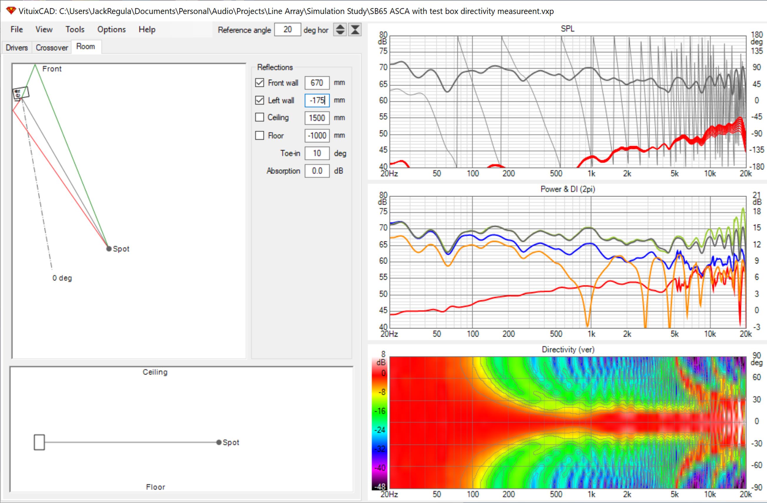
The other side at 530mm has a null near 250 Hz. If you can fit an 8" panel there, that should suffice.
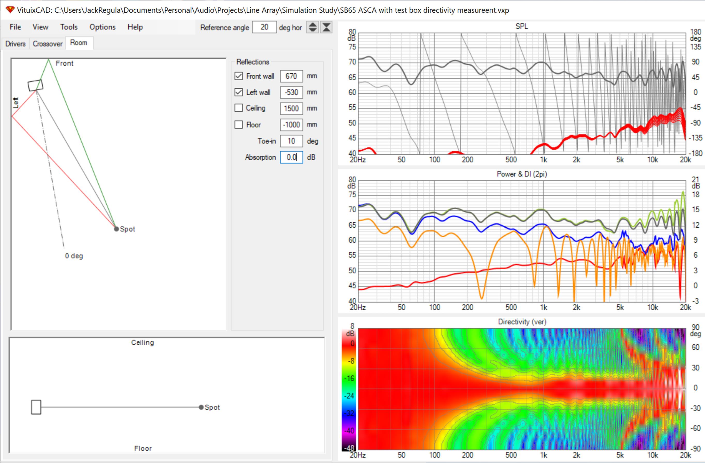
These nulls and ripples are due to the side wall. Turning the front wall reflection on and off has very little effect. Both Wesayso and I have noticed that front wall reflection is the least problematic. I don't want to say it doesn't matter at all because I think the sim might not properly take having to diffract around the baffle into acccount but I would certainly treat the sidewalls first.
Of course I recommend doing your own sim if you haven't already and playing with spacings and absorption.
This comes from my SB65 array sim, imperfectly equalized. The sim predicts the directivity of the array based on measurements of a single driver. At the low frequencies we are concerned with here, the directivity won't be different from a TC9 array. The orange trace in the middle graph is the room response. The gray trace in the top graph is the response at the reference angle without reflections taken into account.
First the close side. The boundary null is out almost to 1 khz where your 2" absorbers will have no trouble killing it.
The other side at 530mm has a null near 250 Hz. If you can fit an 8" panel there, that should suffice.
These nulls and ripples are due to the side wall. Turning the front wall reflection on and off has very little effect. Both Wesayso and I have noticed that front wall reflection is the least problematic. I don't want to say it doesn't matter at all because I think the sim might not properly take having to diffract around the baffle into acccount but I would certainly treat the sidewalls first.
Of course I recommend doing your own sim if you haven't already and playing with spacings and absorption.
Attachments


Thank you NC for the sims, I´ll study them closer later when I get the chance. BTW Left Side distance = 1750mm (1,75m) 😉
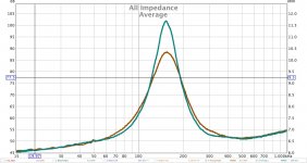
I experimented with the stuffing today and filled one group of drivers, here is the before/after plots. Note that the resistance of my test circuit is not precisely measured so the amplitude may be off, but that shouldnt affect wiggles.
The measurements are from one group of 12 drivers (3Series4Parallell)
One question - comparing mine with Ronald´s I see he have a smooth imp.raise in the HF-range, while mine doesnt - they are all over
Attachments

Last edited:
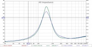
I spent a little time experimenting with the internal damping and came up with a promising combination. So I have now updated my Right array accordingly and Left is not so I could do a comparison.
Right impedance measurement (Brown) is an average of TopRight and BottomRight as each line have two independent groups.
Turqois is average Top/BottomLeft.
I will update the Left with the same damping configuration then I will need to revisit freq.sweeps and speaker positions 🙂
While the freq.scans are rough the ears are still quite excited 😀
Attachments
Finishing up the internal damping for the left line today + sealing the few ones that has a leak. Then I will start to play with speaker positions, room issues and EQ/DSP 🙂
I'm still wondering what happened to your top end on that impedance graph...
I've never seen it look like that...
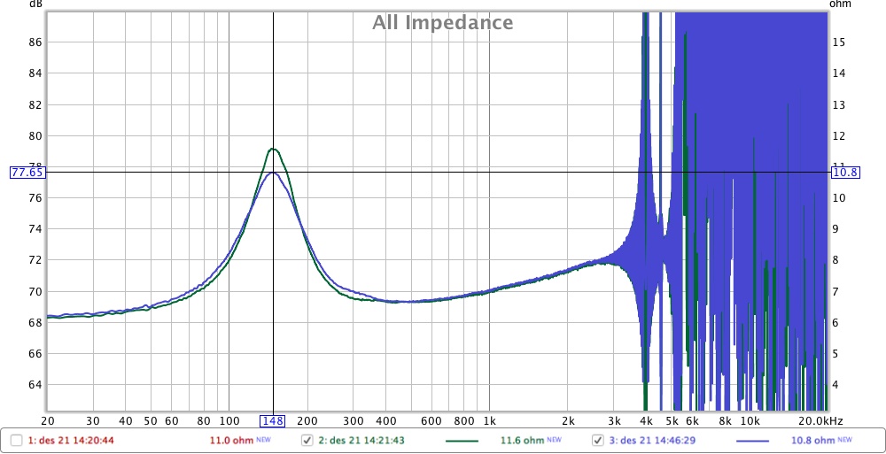
What did it sound like? Just like a normal frequency sweep at reduced SPL? It should be visible in the two most right indicator columns on that meter that's running while making the impedance sweep. The right most indicator draws the impedance curve and should show strange behavior at higher frequencies. But if the tone still sounds like a regular sweep, something must be wrong. The middle (and left) indicator stays at the same level throughout the sweep? It is possible you're clipping the signal somewhere. That could throw everything off. Try running the sweep 3 dB lower in level. Watch the indicators and make sure each of them says clear of the top by a few dB.
I've never seen it look like that...
What did it sound like? Just like a normal frequency sweep at reduced SPL? It should be visible in the two most right indicator columns on that meter that's running while making the impedance sweep. The right most indicator draws the impedance curve and should show strange behavior at higher frequencies. But if the tone still sounds like a regular sweep, something must be wrong. The middle (and left) indicator stays at the same level throughout the sweep? It is possible you're clipping the signal somewhere. That could throw everything off. Try running the sweep 3 dB lower in level. Watch the indicators and make sure each of them says clear of the top by a few dB.
Last edited:
I´ll check that out impedance test levels and get back to you 
Just had a brief listening session downstairs, 3/4 of the system is now re-stuffed and the immideate impression is that the low end is a little more behaved. Imaging is awesome.
The amp shut down again on me for the first time after optimizing the signal cables.
When the latter 1/4 of the system is sealed and re-stuffed aswell I´ll redo SPL/Freq. sweeps and see how that might change things. If the low end wasnt damped properly there will be boominess and raised distortion levels - so it will be nice to compare before/after sweeps and see if my thinking is sound (pun intended 😀 )
Its the upper left group that is due, but this is also the same group where 3-4chambers that leak out the rearside are located. So need to address that at the same time as I have the drivers removed.
Before sweep, I hope added damping will reduce the step between 40-50hz. Damping now consist of 8mm felt on all walls, mineral wool and sheep wool.
Attachments
Last edited:
Maybe you are playing louder without realising it?
//
That can easily happen ... when distortion is incredibly low it’s easy to play way louder than what you think you are doing 😀
It didnt occur to me to test SPL-levels as it was just a quick(😉 test after re-damping the bottom 12 drivers for the left array. (* - quick test that consumed 45minutes in an instant 😱 )
It has happened before that people in the same room, while playing music, may attempt to talk / start conversation...only to realize that nothing is received.
May have limited time over the next few days to play - so I wish you all happy holidays


It has happened before that people in the same room, while playing music, may attempt to talk / start conversation...only to realize that nothing is received.
May have limited time over the next few days to play - so I wish you all happy holidays
Last edited:
Hope there will be some freedom from measuring and stuffing throughout the x-mas days, over here it will of course be the traditional "pinnekjøtt", Akevitt, Hansa Juleøl
Merry Christmas guys
Merry Christmas guys
"Pinnekjøtt" for sure, with all the appropriate "add-ons" 
Both lines are now re-stuffed and operational, will so how that "feels"...
Now its time for family 😀 Merry Christmas!
Both lines are now re-stuffed and operational, will so how that "feels"...
Now its time for family 😀
Merry Christmas!Couldnt resist while the rest of the household is chilling in the couch 
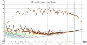
I was curious how the re-stuffing might affect things, which was finished yesterday.
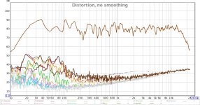
Brief REW-session with UMIK in sweet spot and arrays straight out from the wall (no toe-in), distance to wall approx 90cm. I have not balanced the L/R response individually yet so take it for what its worth
Distortion increase below 100hz obviously with EQ=ON
I was curious how the re-stuffing might affect things, which was finished yesterday.
Brief REW-session with UMIK in sweet spot and arrays straight out from the wall (no toe-in), distance to wall approx 90cm. I have not balanced the L/R response individually yet so take it for what its worth
Distortion increase below 100hz obviously with EQ=ON
Attachments
Last edited:
Between 40 Hz and 100 Hz there are phase differences between both channels. That's creating the suck-out and we need to see the separate left and right plots to figure out the why.
As they do not sum properly, boosting it isn't going to help and distortion will rise quickly.
So we need more detailed information of what's really happening, but that can wait a few more days 😉.
As they do not sum properly, boosting it isn't going to help and distortion will rise quickly.
So we need more detailed information of what's really happening, but that can wait a few more days 😉.
I am learning by doing 🙄
Thanks for the input 🙂 Speaking of input, apparantly I´ve been good this year as I now have a miniDSP2x4HD to play with - which should offer more tools.
But yes, I need to spend some time on the separate L/R speaker first before any serious DSP-effort should be made. How would I best go about that, toe-in each speaker so its directly pointing towards the UMIK, and point the UMIK directly towards the speaker being measured, from sweet spot and equal distance? Or would a different approach be more viable?
At first I would just play with it for a while, no hurry! Let them settle and break in. I think I waited about a month before I started doing anything serious. I had a lot of fun just listening.
Toe in can be played with, find what you like and what works out in the room. It worked best for me to use about 15 degree toe in for both speakers, making them cross behind the sweet spot position. Theoretically it should work to cross in front of the sweet spot, but it looked kind of silly, so that didn't stick.
I've always pointed my mic straight forward (Pointed towards the middle between both arrays) after placing it in the exact sweet spot (I planned ahead that you'd actually would want to sit right there, or you can have the mic placed just slightly in front of that sweet spot seating position, that works too). I point the mic up somewhat toward the halfway point of the arrays. Height of the microphone was always placed at ear height. Choose something that works for you and stick with that so you have a reference to fall back on.
Lots of other options could be used, lately I make several measurements around that sweet spot and average those, but I still follow the method as described above. The averaging helps make the total correction less peaky, averaging out the response somewhat before processing starts. Not bringing huge differences, but it works out pretty good for me. The positions I measure at around the sweet spot all stay within about ~35 cm around that exact sweet spot.
I've used way wider measurements as well, covering a large area, but in a treated room without too many reflections there weren't huge benefits from doing that.
Congrats on getting the miniDSP. That one has some FIR capabilities, right?
Last edited:
- Home
- Loudspeakers
- Full Range
- HalAir Aeralis - Fullrange Line Array (Vifa TC9-18-08)