Thanks Big Guy,
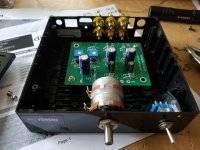
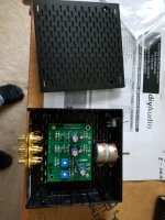
The enclosure is a 1506 size from Ebay. It's actually quite cheap, about £26 to the UK inc. shipping. It came with the volume knob, IEC socket and power switch, I just had to drill for the RCA jacks.
The Meanwell transformer is SMPS, but the board I used (details from Slowdiyer) has some filtering.
Cheers
Neal
Wow! The enclosure is a great homage to the earlier Pass front panels.
As a DIY newbie, did you buy a Slowdiver board with the Meanwell premounted ...or do they need to be bought separately and assembled?
May I impose on you to provide specifics?
Looking at your build photos, there is a board on the backside of the front panel for the control. Is this included in the cost of the enclosure?
Since this build is the H2 V1 R0, what is the pot controlling?
Any guidance will be appreciated.
Be safe, stay well.
As a DIY newbie, did you buy a Slowdiver board with the Meanwell premounted ...or do they need to be bought separately and assembled?
May I impose on you to provide specifics?
Slowdiyer provides the gerber files and schematics, so I had them fabricated by JLCPCB. The parts were bought from RS Components.
Looking at your build photos, there is a board on the backside of the front panel for the control. Is this included in the cost of the enclosure?
Since this build is the H2 V1 R0, what is the pot controlling?
Again, the board for the Alps RK27 pot is from Slowdiyer. If you order both the psu board and the pot board, it shouldn't cost more than about £10 including postage and you would get 5 of each board. I've used the H2 as a preamp so this is the volume control.
Cheers
Neal
Thx Xrk; I received my pair today.
Me too! Thanks again.

Been quiet around here...
so I hope y'all and yours are well.
I would like to ask a question about adjusting the revised H2 which now has a variable pot for each channel. My bag was marked 2.65 but do not understand how this number is used to adjust the pots or what/where requisite readings are taken.
Details would be appreciated.
Thanks.
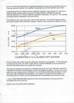
2.65 is your pinch off voltage. With a ruler, intersect vertically with the 2% and 1% lines. For each percentage, look for the voltage setting on the left hand side vertical scale for the voltage to get you to either 1 or 2 percent distortion. To adjust for this, you'll need a meter on T2 and ground.
so I hope y'all and yours are well.
I would like to ask a question about adjusting the revised H2 which now has a variable pot for each channel. My bag was marked 2.65 but do not understand how this number is used to adjust the pots or what/where requisite readings are taken.
Details would be appreciated.
Thanks.
Hello Big Guy.
Please see posts #334, 340, 342 and 343 which elaborate further on the accurate posts by vdi_nenna.
Best
Anton
i have couple of questions,
I have smd version of J112 from another project but its power dissipation is 350mw (to-92 is 625mW) can i use it without any heat issue?
Please confirm that;
To get 2nd harmonics on both positive an negative side i have to invert both, input of H2 and output amplifier.
And finally,
I will use H2 in front of cheap tpa3116 board. The amplifier board gain is 26dB and input impedance is 30 kΩ, any suggestion for H2 paramaters?
i have couple of questions,
I have smd version of J112 from another project but its power dissipation is 350mw (to-92 is 625mW) can i use it without any heat issue?
Please confirm that;
Q2. To get 2nd harmonics on both positive an negative side i have to invert both, input of H2 and output amplifier.
And finally,
Q3. I will use H2 in front of cheap tpa3116 board. The amplifier board gain is 26dB and input impedance is 30 kΩ, any suggestion for H2 paramaters?
Hello potstip,
Reverse the leads of the loudspeaker only for question 2 so as to get either H2 positive or H2 negative phase.
Use a volume control [dual] at the inputs of H2. This is needed because the FET has a voltage gain of ~ 7-10; which will be excessive for any power amp with a voltage gain of 21. Many build examples show a pot; by example the middle image from vdi_nenna's recent post #624.
The dissipation of the FET is calculated by first measuring its Vds [V] and Idss [mA], and then multiplying the two to get Pd. Idss for the standard FET in H2 is roughly 30 mA.
Best
Anton
2.65 is your pinch off voltage. With a ruler, intersect vertically with the 2% and 1% lines. For each percentage, look for the voltage setting on the left hand side vertical scale for the voltage to get you to either 1 or 2 percent distortion. To adjust for this, you'll need a meter on T2 and ground.
Thanks, VDI.
Finally got back to this... Attached is copy of T2 vs Pinch Voltage of 2.57 (Not 2.65 as previously meintioned) with T2 determined to be ~14.6V for 1% distortion and ~14.1V for 2% distortion.
I will record initial V's at both T2 points and adjust for 14.6V.
Is the target output V approx 5V as with H2 Original?
Where is the proper place to measure...between the Out and G for each channel?
Thanks for continuing guidance.
Attachments
sadly, there is no bigger font available

Aptly named, Jester! Glad I could provide fodder...

Good morning Gentlemen,
I am hightly interested by this Mr.Pass H2 harmonic Generator ...
I would like to purchase the PCB or the kit. Please could you precise me where to find it.
I thank you really much for your answer.
Best regards,
TYM
I am hightly interested by this Mr.Pass H2 harmonic Generator ...
I would like to purchase the PCB or the kit. Please could you precise me where to find it.
I thank you really much for your answer.
Best regards,
TYM
For a kit, I believe you will need to find a person willing to part with one.
For the PCBs, you can perhaps find someone to part with one, or you can have PCBs made. See post #223
I haven't seen any in the group buy or swap meet areas.
For the PCBs, you can perhaps find someone to part with one, or you can have PCBs made. See post #223
I haven't seen any in the group buy or swap meet areas.
How big is the chance from a package with 50 x J112 to find matching pairs? Five pairs would be perfect for ordering a little batch of pcbs.
DK = out of stock
RS = min 50 prices
Mouser = only two
Other seller I didn't trust them or they had "funny asking price" (up to 3€ each).
DK = out of stock
RS = min 50 prices
Mouser = only two
Other seller I didn't trust them or they had "funny asking price" (up to 3€ each).