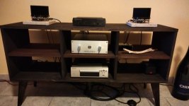
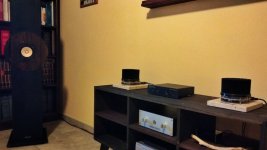
I understand that the easiest solution to inverting the signal would be swapping the bananas around at the speaker if you've got a typical preamp->amp->speaker type thing going on, but I'm using a minidsp shd studio that goes out to a balanced dac that drives a hypex nilai for my main speakers, which doesn't have a single ended input.
So, I could flip those wires I guess, but I'm building multiples of these H2 devices to tinker with, and everything under 60hz goes to a minidsp 10x10 to run multiple subs and midbass units. Those are all neutriks, the easiest way might be to invert the drivers that aren't inverted already in dsp and un-invert the ones that are, but I'm thinking hey, if I can just solder these xlr plugs backwards and then forget about it, that's what my lazy keister is gonna do. 🙂
So, I could flip those wires I guess, but I'm building multiples of these H2 devices to tinker with, and everything under 60hz goes to a minidsp 10x10 to run multiple subs and midbass units. Those are all neutriks, the easiest way might be to invert the drivers that aren't inverted already in dsp and un-invert the ones that are, but I'm thinking hey, if I can just solder these xlr plugs backwards and then forget about it, that's what my lazy keister is gonna do. 🙂
I finished my H2 and have been listening for about a week. I think what I am hearing is more depth to the vocal and base. More resonance might be a way to put. Is that what other people are thinking also? It does have a noticeable hum when there is no music playing. Is that normal?
Tom
Tom
No, check the ground connections on inputs and outputs, especially solder connections.It does have a noticeable hum when there is no music playing. Is that normal?
Did you adjust the bias to 9.5v?
The circuit inverts the phase, try changing the speaker connections so + (from the amp) goes to - (on the speaker) and minus goes to plus.
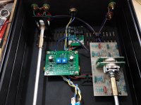
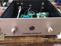
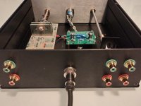
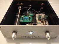
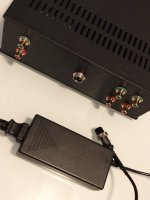
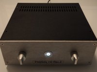
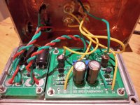
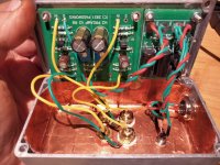
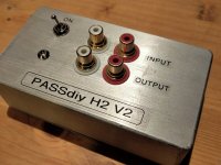
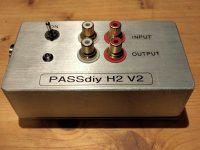
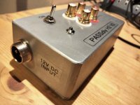
This is what my final build looks like. I used my multimeter to test connectivity between the grounds on the input and output RCAs and they all connect to the grounding ring around the outside of the board. Plus they connect through to the negative of the power plug. Not sure if that means they are all grounded since this is not in a box with a ground wire connected to the box. I adjusted my pots to show 10.71V at T2 since that is what is written on my bag.
Tom
Tom
Looks good. Did you build it for unity gain by changing the resistors? If not, and with no volume pot, it might be caused by running the H2v2 at full gain. I'm not sure if a hum would happen.
Yes, that means they are all grounded.Not sure if that means they are all grounded since this is not in a box with a ground wire connected to the box.
Nelson discussed in the original H2 paper that the circuit is susceptible to noise and should be in a metal case.
You could try using a metal container placed over the circuit board like a hat. I use masking tape around the edges to prevent short circuits from the metal box. Be careful.
No need for a wire from ground to the box. Let the ground "float", no connection to chassis ground. The 12v SMPS is a small enough voltage not to hurt you.not in a box with a ground wire connected to the box.
Thanks. Nichicon gold tune 1mF that I had, too big for the pcbVery nice! What are the capacitors hiding under the PCB?
- Home
- Amplifiers
- Pass Labs
- H2 V2 BUILD
