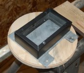
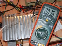
All that trouble? Is it not easier to simply learn how to use valves and get on with it? Anyway, I bought my son a VOX amp which has a valve amp in it which it overdrives to achieve a realistic valve sound, I am not sure if it really sounds like anything special to me. True, when transistor circuits clip, they clip badly, in other words they clip suddenly and precisely without a give, sometimes they clip assymetrically, and sometimes they distort the wave form beyond imagining. That has given them a bad name, but if you design it properly and they do not clip or do bad things to the wave form then they are brilliant.
I have accidentally created some circuits that clipped softly, you could see the curve trying to clip but somehow there was that much extra voltage as if by magic to prevent it from going horizontal, I think this can be achieved when the input signal to one stage carries more energy than the supply source of the stage thereby driving the stage almost. I cannot put my finger on it, but I am sure to see it happening again on the scope and then I will stop and take notes 🙂
I have accidentally created some circuits that clipped softly, you could see the curve trying to clip but somehow there was that much extra voltage as if by magic to prevent it from going horizontal, I think this can be achieved when the input signal to one stage carries more energy than the supply source of the stage thereby driving the stage almost. I cannot put my finger on it, but I am sure to see it happening again on the scope and then I will stop and take notes 🙂
Hi John,
Just modelling static transfer functions of tubes or som mimicking of static clipping is way not enough IMHO to get that described sound (if that is one's preference, of course, some like it more clean/dry/static for some styles)
- Klaus
Thanks Klaus,
I'm just playing with the circuit boraomega presented. I may prototype the changes I made to see how it performs in real life or I may not. Clipping aside, the type of distortion it produces might be interesting.
I will not go to the lengths you outlined above, mainly because I probably wouldn't hear the difference.
All standard regs (LM317 vs LM337 and 78xx vs. 79xx etc) have this different pinout for pos. and neg. regulators, all the negs. are GND/REF -- IN -- OUT (top view). 😡
- Klaus
I meant to test it by reversing the IN and OUT leads. It's just weird that I have 4 regs, 2 positive that are correct and working and 2 negative that are NOT working - all are unused.
IHMO the overall design effort etc is quite the same no matter if the devices are transistors or tubes because it is a conceptual/topological thing and not so much an issue of the parts used (apart from the ouput stage, maybe)... advantage of tubes is that you can recreate (or let yourself get inspired from) known good amp designs while transistors allow for cheaper/easier/safer building (think of the cost of tubes/xformers and hazardous voltages involved etc) and you can do more things, leaving the common roads.All that trouble? Is it not easier to simply learn how to use valves and get on with it?
- Klaus
One step at a time. The amp module is finished, just to give it some more paint to pretty it up. 🙂
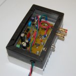
All wired up (except the output inductor, I put that in after this pic) and ready to test. I had to make insulators for the RCA and the positive binding post ( 😡 ). Nice, neat vinyl grommet for the power wires.
Cooking:

Connected to my lab supply at 30VDC, drawing .7 amps. I leave it like this for a while to see how hot it gets and troubleshoot by fire any potential problems.

All wired up (except the output inductor, I put that in after this pic) and ready to test. I had to make insulators for the RCA and the positive binding post ( 😡 ). Nice, neat vinyl grommet for the power wires.

Cooking:

Connected to my lab supply at 30VDC, drawing .7 amps. I leave it like this for a while to see how hot it gets and troubleshoot by fire any potential problems.
@MJL21193
Well, point was to get something like “B” instead of “A”. Graph at B is what I got from simulation.
Thanks,
For some stupid reason, opamps will not clip in Multisim - increase the input voltage and output just goes up, regardless of supply voltage! 🙁
I wanted to see if it achieved "soft clipping" but for the limitation above.
To get around the clipping problem I made my own opamp:
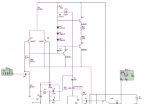
This does clip. 🙂
I returned the rest of the circuit to the original and ran it, driving it into clipping. It didn't round the wave tops, just reduced the amplitude - the flat top of the clipped wave was still there.
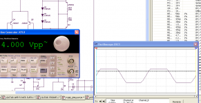
I ran the FFT and the harmonics were once again odd ordered and strong.
No, this doesn't look as good as the changes I made to it. I will try my version with this discrete opamp and decide if it is worth prototyping.
Hiya, I have downloaded Multisim and tested on a simple circuit. But it is not showing me what I expect to see, it rather behaves as if the BC560AP transistor has like 10hfe 🙂 I do not know how to see/edit those parameters, I am trying the help now but if you do know please tell me.
Spice programs are only as good as the models they use - is that a model from the MS library?
To change a model click the device properties, select "edit component in DB", select the "model" tab and go from there. MS has a detailed model maker where you can custom build your own model or you can copy an existing good model from some other source and import it.
It's a bit of work and takes some time getting used to.
Simulation is just a poor-man-delight to give you impression that you’ve done something that cost you nothing. Once you build it you will face the truth. Maybe, one day, simulation will be precise and powerful enough to mimic real world successfully, but till then… I’ll be prone to categorize it as “petting” at best…Spice programs are only as good as the models they use ...
Of course, other people don’t have to agree with that… that is their right!
Spice programs are only as good as the models they use - is that a model from the MS library?
To change a model click the device properties, select "edit component in DB", select the "model" tab and go from there. MS has a detailed model maker where you can custom build your own model or you can copy an existing good model from some other source and import it.
It's a bit of work and takes some time getting used to.
Yes I tried the model maker and failed! I will try again 🙂 All I want is some very common transistors, in Europe at least, bc550c, bc560c, 2n5459, mpsa18, bc327/337, bc 639/640 etc
Simulation is just a poor-man-delight to give you impression that you’ve done something that cost you nothing. Once you build it you will face the truth. Maybe, one day, simulation will be precise and powerful enough to mimic real world successfully, but till then… I’ll be prone to categorize it as “petting” at best…
Of course, other people don’t have to agree with that… that is their right!
It's funny how most of the circuits that I simulate work in nearly the identical way when I build them. 😕
Of course there are limitations, as there are on all tools.
It's funny how most of the circuits that I simulate work in nearly the identical way when I build them. 😕
Of course there are limitations, as there are on all tools.
Certainly, why not... it happens to me many times but still.......
LTSPICE works fairly well. It's opamp model does seem to clip correctly when you overdrive the inputs - but then opamps is one of LT's key areas.
Models - yes this is a thorny one. I get most of mine from Fairchild. Onsemi have some rediculously wrong ones, eg the BD139/140 and MJE340/350 models are useless.
Models - yes this is a thorny one. I get most of mine from Fairchild. Onsemi have some rediculously wrong ones, eg the BD139/140 and MJE340/350 models are useless.
I've posted a simple universal (idealized) single pole opamp model with output clipping at the supplies recently in the SPICE thread. It also reflects the output current into the correct power pin of the opamp, and an output resistance and some quiescent current is also modelled. All parameters can be overriden. Here it is: http://www.diyaudio.com/forums/showthread.php?p=1877789LTSPICE works fairly well. It's opamp model does seem to clip correctly when you overdrive the inputs - but then opamps is one of LT's key areas.
Alternative (but at the cost of processing speed) is to use a good and complete opamp model (apart of distortion which is never modelled correctly), like TI's OPA211.
Most LT opamp models supplies with LTspice s*ck, (not only) in this regard
- Klaus
Last edited:
LTSPICE works fairly well. It's opamp model does seem to clip correctly when you overdrive the inputs - but then opamps is one of LT's key areas.
Models - yes this is a thorny one. I get most of mine from Fairchild. Onsemi have some rediculously wrong ones, eg the BD139/140 and MJE340/350 models are useless.
I haven't tried all of the opamp models so I can't say every one acts the same way. My change to the "tube emulator" boils down to giving the MOSFETS some current. I'll perf board it and see how it sounds (and if it actually rounds the wavetops), with or without the current.
I have captured the schematic for "The Big Muff" and this effect will be on board. So we have reverb, tremolo, big muff and (possibly) tube tone. Should be fun to learn on. 😀
When I got home this evening I had a slip in my mailbox to pick up a package at the post office - I expect that's my reverb tank and LDR.
😎
More fun to come.
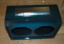
PS: Construction details of the box are found here: Groovy Guitar Amp
This is what I use for getting a good valve type sound from my guitar.
An externally hosted image should be here but it was not working when we last tested it.
This is what I use for getting a good valve type sound from my guitar.
This is interesting! I just ran this and it seems to do what the other was claiming to do - namely round the clipped wave tops! The harmonic spectrum looks correct also.
This is worth looking further at. Thanks Nigel!

LTSPICE works fairly well. It's opamp model does seem to clip correctly when you overdrive the inputs - but then opamps is one of LT's key areas.
Models - yes this is a thorny one. I get most of mine from Fairchild. Onsemi have some rediculously wrong ones, eg the BD139/140 and MJE340/350 models are useless.
But I did nothing as complicated as an op-amp. Actually it was 3-4 transistors and the problem was pinned down to 1 transistor, it seems it thought that it presented a very high load (ie a very low impedance) and therefore loading excessively the previous stage. Considering the circuit uses the 10:1 rule the "load" should be insignificant, yet as soon as I connected that transistor the model seemed to think it was very near a short circuit.
I used the "BC560AP" transistor as provided by the package. I then thought there must be something wrong with this transistor (in multisim, not in real life) and tried to make my own, unsuccessfully.
If anyone knows of a low signal transistor which is modelled correctly in multisim, I just need a NPN and a PNP to model the BC550C and BC560C. The params are hfe>520, ft=150MHz and output cap = 4pF, Ic max = 100mA and power=500mW.
Additionally I would also like the equivalent to BC327/337 (PNP,NPN) which is hfe>400 and IC max = 500mA I think, as well as BC639/640 (NPN, PNP) which is Ic max = 1A.
Armed with the above 6 transistors I can get on with most simulations.
- Status
- Not open for further replies.
- Home
- Live Sound
- Instruments and Amps
- Guitar Amp Design / Build
