Here is a link to a valuable site with tube characteristics and documentation:How much power is expected ? What is the impedance of the OPT ?
electron Tube Data sheets - G
Specifically, the GU-81 that I am using is this one:
http://frank.pocnet.net/sheets/175/g/GU81.pdf
My quiescent point is at Ia = 250mA, Ua = 1400V, U_s2=600V.
In my new "S3_HV_UL" topology, the crazy U_s3 = 1400V, connected via OPT to B+, but with an S3_Anihilation_Limiter = 1000 ohms / 20 Watts.
Without any such resistor, the S3 tends to melt / explode / evaporate / disintegrate / disappear. Slightly dangerous. Thank Goodness that I used a variac to test that initially.
Very nice. Classical but nice. The Power supply is familiar. Similar to the one I have, slightly different configuration, but same topology. So you suggest to go for a dual symmetrical voltage feed for a simple Cathode Follower pair ?
Hmmmm ..... I think I like it.
The more so that I have a few additional power transformer tappings which I could use for this ...
Ziggy
Yes , I think that DC coupled CF triode drivers bipolar supplied is very good solution from many reasons , one reason is that you can easy drive OPS in A2 /Ab2 class of operation without to raise significantly THD factor , you can even consider another types of tubes for drivers as 6V6 , GU50 .....
And I think that your expectation for only 100W of output power in A class region is to modest , my rough calculation says that will be around of 250W .
Correction: It is 6000 ohms (anode-to-anode).How much power is expected ? What is the impedance of the OPT ?
But you calculated it based on "your" schematic, yes ?my rough calculation says that will be around of 250W .
I was looking at it through my "auto-biased" topology and my less-than-optimal OPT with 6000 ohms and B+ voltages ...
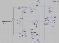
I am trying to envision potential "disaster scenarios".Here is the quick concept draw , ...
a). If the driver tube in wiggles / gets a mis-contact in its socket, then we are on the safe side, as the GU-81 grid gets the -200V on it's grid and is cut off ... correct ? The transformer will be saturated by the current of the other tube, but that is not in itself a disaster, is it ?
b). If the bias setting pot fails on the driver tube ... like a slider miscontact ... that smells like potential disaster. Grid is unbiased, the driver tube starts conducting heavily, GU-81 grid gets a big positive bias and we are in trouble.
But I think that If I add an additional fixed safety resistor, an "anti-pot-failure" resistor, and place it between the slider of the pot and the negative voltage end of the pot, then we are "safe" yes ? In the case of slider mis-contact, the driver's grid gets a much higher negative bias, the driver shuts off, and consequently the GU-81 also shuts off ... Correct ?
Last edited:
But you calculated it based on "your" schematic, yes ?
I was looking at it through my "auto-biased" topology and my less-than-optimal OPT with 6000 ohms and B+ voltages ...
- Yes .
- Auto bias(cathode bias) for mighty 2 x GU81 in PP ??? , no way , that`s wrong idea !

I am trying to envision potential "disaster scenarios".
a). If the driver tube in wiggles / gets a mis-contact in its socket, then we are on the safe side, as the GU-81 grid gets the -200V on it's grid and is cut off ... correct ? The transformer will be saturated by the current of the other tube, but that is not in itself a disaster, is it ?
b). If the bias setting pot fails on the driver tube ... like a slider miscontact ... that smells like potential disaster. Grid is unbiased, the driver tube starts conducting heavily, GU-81 grid gets a big positive bias and we are in trouble.
But I think that If I add an additional fixed safety resistor, an "anti-pot-failure" resistor, and place it between the slider of the pot and the negative voltage end of the pot, then we are "safe" yes ? In the case of slider mis-contact, the driver's grid gets a much higher negative bias, the driver shuts off, and consequently the GU-81 also shuts off ... Correct ?
For any worst case scenario in my schematic you have there standard HV slo-blo fuse in 1,2KV B+ supply line , and two 10R/10W resistors in GM81 cathodes circuits , so if OPS from some reason draw some abnormal current ,or if OPT fail , something from those two elements will blow and OPS will be protected .
Yes, it "is wrong". I know. But I was going the route of "better safe than sorry" ... and it saved my skin a couple of times already. When I grow up to the concept, I will junk the auto-bias and do it with CF. I like the concept.- Yes .
- Auto bias(cathode bias) for mighty 2 x GU81 in PP ??? , no way , that`s wrong idea !
I like the concept.
Cool !
But as I say earlier this concept it is nothing new , Philips was used this concept for several mid-power & high-power audio amps , and also few other manufacturers to.
Edit , for security reason you can also consider one slo-blo fuse on 0,6KV - G2B+ line .
Last edited:
Banat, what is the Ra-a at your power calculation (250 W) ?
I did not made any calculation for Raa but only fast&rough calculation of A class output power region based on GU81 specs .
I made some quick LTSpice simulations with push pull circuit.
The operating point was: Ia = 238 mA, Ig2 = 65 mA, Ug1 = -127 V, Ua = 1.2 kV, Ug2 = 600 V. OPT series resistance was 200 ohms anode to anode.
I varied the OPT impedance between 5k to 8k2. The performance in general and linearity seems not to be sensitive for load impedances I used.
Some sort of max. output power is about 350 W and THD then is from 3.5 % to 4.5 %. Below 200 W THD is about 1% to 1.4 %.
The screen stoppers should be as small as possible (<100 ohms). These have strong effect to available output power.
I don't see any reason for cathode follower drivers. G1 voltage stays allways far from grid current area.
Attachments
Last edited:
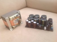
That transformer is 2 x 195 V. What anode- and g2-voltage you plan to have ?
How about the filaments ?
It would be interesting to see the schematic.
How about the filaments ?
It would be interesting to see the schematic.
Speaking of output tube filaments, which require 12,6V @ 10,5 A, what would you consider as the preferred option:How about the filaments ?
a). A toroidal transformer with 12V output and sufficient current capability,
c). A plain vanilla SMPS, of type MeanWell SP-150-12
d). As c). but with additional CLC, where C=150000uF/16V || 1uF foil || 47nF and L is a few bifilar turns CMC choke on a ferrite core
e). A toroidal transformer, rectifier, filter, and then Voltage source
f). A toroidal transformer, rectifier, filter, and then a Current source
g). A toroidal transformer, rectifier, filter, and then a Voltage source, followed by a Current source.
h). None of the above.
Are you asking me ?
I am asking Koifarm how he plans to do this.
I do not have too much practical experience with direct heated tubes.
I have built one 811A and a 813 SE prototype with AC-filaments.
I got > 65 dB S/hum, so propably I would try the same principle.
I think playing with current sources is useless.
I am asking Koifarm how he plans to do this.
I do not have too much practical experience with direct heated tubes.
I have built one 811A and a 813 SE prototype with AC-filaments.
I got > 65 dB S/hum, so propably I would try the same principle.
I think playing with current sources is useless.
Last edited:
That was a general question to all the participants of this thread, rather.Are you asking me ?
Just curious.
The reason why I ask is that recently I had a heads-on argument with a guy who made it on SMPS supplies, with output filtering. Indeed, no hum ... nothing. Seems to be an unorthodox, but "reasonable" way to go, or at least to try it out.
See post 63 for the schematic.
I use cheap chinese SMPS for the heaters in several direct heating amps. No hum or noise at all. at the moment i use a fu13(813) amp to.
I run the smps with NTC resistor to slow down the startup current.
I use cheap chinese SMPS for the heaters in several direct heating amps. No hum or noise at all. at the moment i use a fu13(813) amp to.
I run the smps with NTC resistor to slow down the startup current.
Attachments
Last edited:
I use cheap chinese SMPS for the heaters..
Can you suggest any supplier ?
Do you have one SMPS divided for both GU81's ?
- Home
- Amplifiers
- Tubes / Valves
- GU-81m tube amp schematics???