T-Reg on itself is a very light load, just a few mA. Sizing for that isn't a good way.
You need to determine the load on the T-Reg, the circuit you want to power, and use it's resistor equivalent as the R2 load to your supply.
Jan
You need to determine the load on the T-Reg, the circuit you want to power, and use it's resistor equivalent as the R2 load to your supply.
Jan
Actually, now that I've thought about it, the load would be all the power the circuit uses. That would be a lot of power, it runs hot!!
if P = I x V
and I want to run 2 kt88s at 450V then (0.14A) x (450V) = 63W
I have 2 kt88s so 126W
and then 4.5W for the 12AT7
About 130W total.
Is that closer to what I'm looking for? Everything in audio is way more complicated than it appears at first glance! Whenever I think I understand something about circuits I soon realize how much the Dunning Kruger effect applies to me!! 🙄
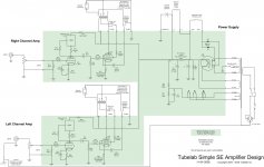
You said it: 2 x KT88 at 140mA each is 280mA, say 300mA to be on the safe side. That's what the T-Reg has to deliver, at 450V. Equivalent load on PSUD2 is thus 450V/300mA = 1.5k
Jan
Jan
Thanks for the explanation. That changes the circuit. Looks like I need to lower C1 to about 47uF or the line on the graph looks like a guitar string that's been plucked!You said it: 2 x KT88 at 140mA each is 280mA, say 300mA to be on the safe side. That's what the T-Reg has to deliver, at 450V. Equivalent load on PSUD2 is thus 450V/300mA = 1.5k
Jan
Cool, thanks for the help Jan 🙂
I recently received word from Mouser that the FDP12N60NZ is obsolete, discontinued by the manufacturer.
https://www.mouser.com/ProductDetail/512-FDP12N60NZ
They still have a good number in stock (1200) but it may at some point become a problem. I’m wondering if I should stock up on a spare or two in case I need to replace that component some years from now unless there is a suitable substitute.
https://www.mouser.com/ProductDetail/512-FDP12N60NZ
They still have a good number in stock (1200) but it may at some point become a problem. I’m wondering if I should stock up on a spare or two in case I need to replace that component some years from now unless there is a suitable substitute.
I don't have a part number handy right now but I am pretty sure there will be an alternative.
Give me day or so to find one.
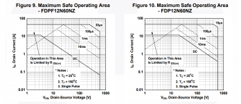
Edit: Onsemi recommends a replacement FDPF12N60NZ which is the isolated fullpak version.
The problem lies in the very much reduced SOA as shown in the attachment.
At 600V across the device (shorted output T-reg) the FDP60 can handle 400mA, the FDPF60 only 70mA ...
Jan
Give me day or so to find one.
Edit: Onsemi recommends a replacement FDPF12N60NZ which is the isolated fullpak version.
The problem lies in the very much reduced SOA as shown in the attachment.
At 600V across the device (shorted output T-reg) the FDP60 can handle 400mA, the FDPF60 only 70mA ...
Jan
Attachments
Last edited:
A good replacement would be the NTP110N65S3HF. But there is an error in the datasheet. There is also a fullpak version, the NTPF110N65S3HF which has a much smaller SOA (due to the extra isolation of course).
Unfortunately, if you look at the data sheets it's clear that they messed up the SOA curves for the two types.
I need to straighten them out again 😎
But to answer the original question: the NTP110N65S3HF is a good replacement. I will add it to the BOM.
Jan
Unfortunately, if you look at the data sheets it's clear that they messed up the SOA curves for the two types.
I need to straighten them out again 😎
But to answer the original question: the NTP110N65S3HF is a good replacement. I will add it to the BOM.
Jan
About senior moments: Over the weekend I built 4 more T-Regs. Bench testing the first one I noticed output followed the input without any regulation. Reason was I mixed up Input and Output. The regulator survived without damage and hooked up the right way around works perfectly fine.Don't start me about my own senior moments ... !😎
Jan
OK yes I can see why that didn't damage anything, the diode in parallel with the FET shorted out any bad polarity voltages.
Good to know!
Jan
Good to know!
Jan
Hi Jan,
im thinking of building a few of these. I’ve looked through the documentation, but other than the temperature rise table in the article and mention of ”see text” in the bom, I can’t find explicit instructions on how to work out the dissipation in Q1/Q7. Any advice appreciated.
Raja
im thinking of building a few of these. I’ve looked through the documentation, but other than the temperature rise table in the article and mention of ”see text” in the bom, I can’t find explicit instructions on how to work out the dissipation in Q1/Q7. Any advice appreciated.
Raja
The dissipation is simply the voltage across the device times the current through the device.
P = V x I (watts, volts, amps).
Jan
P = V x I (watts, volts, amps).
Jan
360V @ 60 ma for a 300B (sophia electric princess)
D3A at 150v @ 15mv
Input voltage 400V or so.
it’ll need a tasty heatsink…
D3A at 150v @ 15mv
Input voltage 400V or so.
it’ll need a tasty heatsink…
It’ll be the 400v input being regulated to 360V, Jan. the driver voltage is dropped via a choke and resistor.
ah, I thought you meant the total draw needed to be taken into account.So 40V. At 60mA +15mA. How much power is that ;-)
Jan
Yes. Isn't that 60mA + 15mA?
Or is that for one channel?
Are you able to calculate the dissipation? I gave the simple equation earlier.
How did you arrive at 30W?
Not trying to play games - I think if you apply this stuff you should know what you are doing.
Jan
Or is that for one channel?
Are you able to calculate the dissipation? I gave the simple equation earlier.
How did you arrive at 30W?
Not trying to play games - I think if you apply this stuff you should know what you are doing.
Jan
- Home
- Group Buys
- Group Buy for Jan's high voltage regulator