The amps are monoblocks, so it would be 75ma dissipated across the transistor for each amp.Yes. Isn't that 60mA + 15mA?
Or is that for one channel?
Are you able to calculate the dissipation? I gave the simple equation earlier.
How did you arrive at 30W?
Not trying to play games - I think if you apply this stuff you should know what you are doing.
Jan
30W is the approx total power consumption of each amp, Jan.
OK, you won't come clean. Your choice.
75mA per channel, with 400-360V=40V across the regulator, is 40 x 75 mW = 3W per channel in Q1/Q7.
Jan
75mA per channel, with 400-360V=40V across the regulator, is 40 x 75 mW = 3W per channel in Q1/Q7.
Jan
i thought you understood my mistake, which was summing the amp power consumption with p=va. This wasnt about coming clean. I didn’t think I’d need to tell you how I arrived at the figure. Assumption got the better of both of us.OK, you won't come clean. Your choice.
75mA per channel, with 400-360V=40V across the regulator, is 40 x 75 mW = 3W per channel in Q1/Q7.
Jan
I asked clear question, you tap-danced. I'm not spending my time on such games.
Off to my ignore list.
Jan
Off to my ignore list.
Jan
Hello Jan,
Are C3, C4 , C6 and Q1 voltage rating are limited factor why the board is limited to 500V in? If changing these components to higher voltage rating, would it be safe for input higher than 500V? My supply has about 640 V raw output after choke/capacitor input filter. I could reduce the supply further with some power resistor to bring it about 600V or less as required. However, I wanted the flexibility to adjust it between 400-550V regulated output with load current of 250mA for testing different amps. Will plan to use chassis heatsink for Q1. With these in mind, would it safe to use your board or I need to do something else? Please let me know. Thanks.
Are C3, C4 , C6 and Q1 voltage rating are limited factor why the board is limited to 500V in? If changing these components to higher voltage rating, would it be safe for input higher than 500V? My supply has about 640 V raw output after choke/capacitor input filter. I could reduce the supply further with some power resistor to bring it about 600V or less as required. However, I wanted the flexibility to adjust it between 400-550V regulated output with load current of 250mA for testing different amps. Will plan to use chassis heatsink for Q1. With these in mind, would it safe to use your board or I need to do something else? Please let me know. Thanks.
Actually you can use it up to 600V with one change. Q8 is shown as a IXTP08N100D2, which were not available at the time I assembled the kits.
So replacing the IXTP08N50D2 with a IXTP08N100D2 gives you 600V limit.
C3, C4 and C6 should be 630V rating.
Jan
So replacing the IXTP08N50D2 with a IXTP08N100D2 gives you 600V limit.
C3, C4 and C6 should be 630V rating.
Jan
Jan,
Yes, I am aware of the Q8 and will use IXTP08N100D2. I probably will use higher voltage rating for C3 too to give it more safety margin and peace of mind. Also do you have any concerns if I replace Q1 with IXTP08N100P? I have both Q1 and Q8 in my hand. Yes, I am aware it does not have Vgs protection built in as FDP12N60NZ. However, I will find the way to add them in.
Again, thanks for a quick response.
It all depends on the current draw. The 12N60 can source 400mA and still be short-circuit proof with its large SOA.
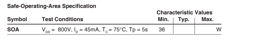
The IXTP08N100P will be limited to 100mA at 25C heatsink, and only half that at 75C. (see fig 15 and 16 of the data sheet).
Is that within the intended envelope?
Jan
The IXTP08N100P will be limited to 100mA at 25C heatsink, and only half that at 75C. (see fig 15 and 16 of the data sheet).
Is that within the intended envelope?
Jan
That's funny, I found it in the attached.Jan,
I can't find the SOA figures 15 & 16 of IXTP08N100P in datasheet that you just mentioned. Attached is the datasheet.
Edit: it's gone now that I attach it! Weird. I added a screenshot.
There's also a one-line spec in the datasheet, attached.
Jan
Attachments

Jan,
There are two different datasheet for IXTP08N100P (Enhancement) and IXTP08N100D2 (Depletion). IXTP08N100P does not have figures for SOA. However, I assumed that we can use the same SOA from IXTP08N100D2. Now I can see your point. In my situation for normal operation with 50-60V across Vds I think it will be OK but not look good for 200Vds. It's definitely not short proof.
Again thanks.
OK, yes I missed that difference. But you get it.
I have spend countless hours searching datasheets for a good HV FET with a wide SOA, they are rarer than hen's teeth.
Nobody is using FETs in linear mode except those funny audio guys 😎 .
The 12N60 is being obsoleted as well.
Jan
I have spend countless hours searching datasheets for a good HV FET with a wide SOA, they are rarer than hen's teeth.
Nobody is using FETs in linear mode except those funny audio guys 😎 .
The 12N60 is being obsoleted as well.
Jan
Very good question! What I did in the T-reg is to make sure that the current at the current limit does not stay there more than a few 100mS.
In case of short, the current is limited to the set value but a fraction of a second later the supply is shut down.
The idea is that short-term load pulses at the current limit are supported but only for very short periods.
It's a bit of guesstimate work, but in practice it seems to work.
Jan
In case of short, the current is limited to the set value but a fraction of a second later the supply is shut down.
The idea is that short-term load pulses at the current limit are supported but only for very short periods.
It's a bit of guesstimate work, but in practice it seems to work.
Jan
Jan,
I noted on your website you recommended that NTP110N65S3HF would be a good substitution for FDP12N60NZ. During my research I found a few that would probably be good candidates for substitution that you want to take a look (e.g., STP36N60M6, STP33N60M6, STP34N65M5, STP35N60M2-EP).
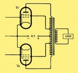
On another subject I plan to connect your regulator to the B+ of my KT88 pushpull amp with an Ultralinear output transformer, do you see any issue with this or what other recommendation you would recommend to do before connect it to the B+ (H.T)?
Thank you.
I noted on your website you recommended that NTP110N65S3HF would be a good substitution for FDP12N60NZ. During my research I found a few that would probably be good candidates for substitution that you want to take a look (e.g., STP36N60M6, STP33N60M6, STP34N65M5, STP35N60M2-EP).
On another subject I plan to connect your regulator to the B+ of my KT88 pushpull amp with an Ultralinear output transformer, do you see any issue with this or what other recommendation you would recommend to do before connect it to the B+ (H.T)?
Thank you.
Attachments
Yes these look like good candidates. Too bad the SOA graphs stop at 10mS, but they are quite robust at 1A and 600V or more.
They would probably be totally safe in the T-reg up to say 200mA.
One issue to be aware of is that nowadays many power FETs are offered in a fullpak case which is a totally isolated tab, so you don't need an isolation between the tab and a heatsink.
But fullpak devices have a very bad SOA and are pretty much unusable in a T-reg.
I don't see any problems in your use case. I have been in a discussion with someone who had problems with a choke loaded single ended amp.
But that didn't get resolved whether it was a supply issue or whether there was another issue with the amp.
Jan
Jan,
For Q1 mounting to chassis is it possible to run the wires from PCB to the chassis location where Q is mounted? What precautions or practices I would take into consideration if doing this? Thanks.
For Q1 mounting to chassis is it possible to run the wires from PCB to the chassis location where Q is mounted? What precautions or practices I would take into consideration if doing this? Thanks.
Hi I'm new to the group, this is my first intervention. i am building a phono preamp
purchased two reg ht shunt boards for use in the first voltage gain stage of my phono stage. The stage works in a voltage point of 105V and 8 mA of anode current. What current should I adjust the output shunt to get the best sound result? I have read that other models of shunt (Salas SSHV2) work in an optimum of double or 3x the current necessary for the amplifier stage, in my case with 8mA I should set the shunt to 16-24mA. correct?
I await suggestions.
thank you
- Home
- Group Buys
- Group Buy for Jan's high voltage regulator