But , you fail to consider my use of the 1381/3503 = cascode.
Why so complicated?
Go to straight common base VAS:

The ZTX957 is 85MHz at 100mA, the KSC3503 is 150MHz at 10mA, so the 3503 will be faster in application. At low frequencies the ZTX957 might perform better than the KSC3503, but HF performance will depend on how well you can drive the base and how well you can manage it's lower GBW contribution.
Early voltage is 270 here:
Measuring the Early voltage "VA" of some PNPs at 8mA
How about BF620/622?
That is funny , I could become yet another "snakeoil" salesmen here at DIYA...
I believe we have more than sufficient.😉 I like the fact your stuff is based on real data, but it can still have a catchy name to help "sell" it.
Why so complicated?...
Hi Pavel Nice and simple but I expect the Loop Gain would be less than desirable. Post the ASC and let's simulate it and see.
Best wishes
David
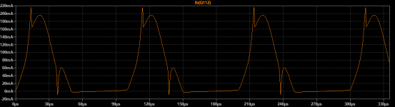
OS, If you can just post scope shots of base current of the Sankens while near clipping at 4ohms, that will still be helpful for improving the models. Currently the models show base spikes when entering quasi-saturation and it would be interesting to see if this reflects the behavior of the real devices.
This is a good option for the VAS as Samuel Groner has shown, although it adds some extra complexity:
https://www.edn.com/design/audio-de...Part-2--Biasing--stability-and-AC-performance
This is a good option for the VAS as Samuel Groner has shown, although it adds some extra complexity:
https://www.edn.com/design/audio-de...Part-2--Biasing--stability-and-AC-performance
Last edited:
Nice and simple but I expect the Loop Gain would be less than desirable.
Just add [DEL]water[/DEL] opamp...
😉
Around 60 dB depth at 10 kHz in simple case, or up to 100 being empowered with proper opamp:
Opamp + Common base
Post the ASC and let's simulate it and see
Oh, let me know how much and what quality of dB’s do you prefer?
😉
OS, If you can just post scope shots of base current of the Sankens while near clipping at 4ohms, that will still be helpful for improving the models. Currently the models show base spikes when entering quasi-saturation and it would be interesting to see if this reflects the behavior of the real devices.
Here is the 2SC6145 base current, with Vce=1.25V and Ic=2,5A.
Sajti
Attachments
Nevermind, I was seeing the base spikes on the Greenamp, I don't think you could get close enough to the rails on a normal amp to see them.
They were not caused by the switching, but the class G circuit caused very low Vce which caused the spikes. Hmm.
This is with the 4.7V zeners replaced with 8.2V. 10KHz.
They were not caused by the switching, but the class G circuit caused very low Vce which caused the spikes. Hmm.
This is with the 4.7V zeners replaced with 8.2V. 10KHz.
Attachments
Last edited:
This is a good option for the VAS as Samuel Groner has shown, although it adds some extra complexity:
Yes, i’ve ideas to go ahead and keep only one external feedback, for allowing as much as possible feedback depth around OPS and inside its bandpass.
On a side but related note, when will diyaudio post an SMD soldering tutorial!? I for one could use / need the education. This project will apparently make it a necessity.
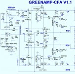
He can’t cope with high gain of this structure and so threw away all of the intrinsic benefits.as Samuel Groner has shown
First of, input stage LTP’s are totally wrong loaded to the low impedance emitters of the second gain stage.
There are at least some kind of followers must be placed inside green circles, this adds at least 40 dB of the so needed gain.
Second of, he shunts the gain of the main gain stage, red X shows the worst case of the correction, high-impedance/high-swing to high-impedance/high-swing point. There are so much high-swing effects in the even high-stability NP0 ceramics, that this approach doesn’t deserve even commenting. Adds at least 40 dB gain at 100kHz range.
Third of, the main stage, which are so needs that tons of feedback stays unlooped! It’s better to have errors in the genetic code than show this nonsense... This is the main goal of the feedback loop - correct total error and reduce output resistance.
So, ok, he show very good topology, but doesn’t comprehend it.

He can’t cope with...
It’s better to have errors in the genetic code than show this nonsense...
Is that how you would talk about me or OS if we posted the same design? Is anyone exempt from this over-baked cynicism?
I think the point was to write an article about a gain stage, not create the "best" amplifier. Why would you beat him over the head with the theoretical shortcomings of a design which he made for demonstrative, educational purposes and gave away for free to everyone?
Of course no, this is not question at all!Is that how you would talk about me or OS if we posted the same design?
I have no doubt, you know the difference between diy/hobby resources and professional sphere like modern universities, high-demand engineering, high-tech science, etc... There are a deep canyon in terms of knowledge, science, universe between them.
So, have no doubt, all of us here at diyaudio are like a hard-welded layers in a damascus steel neighborhood! But also have no doubt that outer resources, especially professional ones, will be investigated with ultrahigh-quality microscope, deep as earth core is and lond as light university path is.
Please let me stay at the light part of the power and keep some of my criticism for anybody outer against our community.
Please let me defend myself!I think the point was to write an article about a gain stage, not create the "best" amplifier. Why would you beat him over the head with the theoretical shortcomings of a design which he made for demonstrative, educational purposes and gave away for free to everyone?
Overbaked - yes, agree.
From time to time we need a huge impact while can’t go further. We search for a sophisticated mentor, we look around, always we found nothing. There are no light at the end, there are deep ugly darkness in the future.
Sometimes somebody, who walk that way with easy, says us - look ahead, your methods are not as clear as they could, your knowledge not so comprehensive that it could be, your work doesn’t shine!
Not so often this sophisticated one will be kind, usually not. He joke about our undergraduation.
So, excuse me for my excessive and maybe overpersonised criticism. Thank you for pointing me to.
Nuff said. It's just I've said stuff on the internet that I regret, and I wouldn't wish that on anyone.
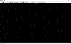
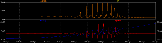
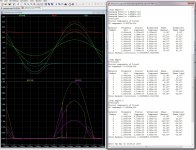
My latest 2SA2223 model revision shows some interesting behavior with the greenamp simulation. Oscillation at the negative peaks.
The oscillation starts at 6.5MHz, then when the predrivers overload, 39MHz pops up in the deadtime.
When the predrivers overload, they then act as rectifiers into the predriver suckout cap, pumping up it's voltage. This then results in the predrivers turning more off. This sequence of events interacts with the suckout capacitance. A large cap will absorb more current before the predriver bias is affected, but will take longer to discharge after the oscillation stops. A small cap will not regulate the bias as well, but will return to normal the instant the oscillation stops. Which is hopefully irrelevant, because we have designed the amp not to oscillate. But interesting nonetheless.
Attachments
You found my super-pair ... 39.4 Mhz
(below).
Edit - you are slick , did it through operation ... not a bode.
OS
(below).
Edit - you are slick , did it through operation ... not a bode.
OS
Attachments
Last edited:
Feedback is also "the mother of invention".
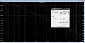
Went on a bode plot/middlebrook "witch hunt".
I can still see a slight hump at 39Mhz , but reduced it considerably.
I saw 39Mhz on my EF3 simulation , but it was -6db lower.
@ 39mhz , there is now -24db gain , 35Mhz is the 180 degree point.
At unity gain , I still have >80 degrees of phase left.
[ This means at >2 Mhz , the amp has strong negative gain. This
strongly prevents oscillation] .
Since I saw the "hump" on both output stages (EF3 and greenamp) ,
it IS the super pair. A bit higher base stopper - -6db on the greenamp.
Greenamp's class H seems to highlight the super pair.
In my witch hunt" , I now have a "super greenamp".
Nearly any THD change with/without class H utilization. (BELOW).
PS - working on PCB + BOM. Actually , ... I am changing the design
slightly for the nearly ALL SMD input stage. New zener series regs
for the diamond/servo, This eliminates the 100uf caps and the IPS
only consumes 36ma total. The IPS will be ICE COLD. (BELOW 2).
Attachments
Last edited:
You found my super-pair ... 39.4 Mhz
(below).
This was one of the issues that I noticed when I said it was possible to "raise the bar"
It's not a disaster but it should be possible to do better - with a small adjustment of the Return Ratio.
I continue to experiment with it, I am a little slow on this because I am not so familiar with CFA compensation - it's a little different.
I left my previous attempts unfinished when I was not quite satisfied, time to dust them off.
Best wishes
David
with a small adjustment of the Return Ratio.
Or do I have to figure it out ? Elaborate.
OS
Or do I have to...?
No you don't have to, I said I would do the work so I will try to deliver on that.
Best wishes
David
- Status
- Not open for further replies.
- Home
- Amplifiers
- Solid State
- GreenAmp ++ modulated Class G output