Sorry, I was thinking of the wrong transistor. Duh. It's pretty close but I don't think it's quite there. BTW, isn't it a Boxall circuit, not Baxandall?
Hmm. I'll tell you what I should have been doing the instant I learned how to do quasi-saturation. Don't use the Hfe vs Ic charts. A model fitted to one of those is actually a very poor representation of how a transistor will behave.
Instead fit the model directly to the Ic vs Vce graph (the quasi-saturation parameters make this worthwhile). You can tune Bf, Ise, Ikf, Nk, and all the quasi-saturation parameters with that one chart, as well as Vaf if it's not very high.
If you learn modeling by trying to fit the Hfe vs Ic curve, you might need to unlearn a lot of things. This is just a vertical slice of the Ic vs Vce chart. You NEED all the extra data and complexity in the Ic vs Vce chart in order to see what the model is doing, and so you can tell the difference between what needs adjustment and what is a deficiency in the model which must be managed. And when you have all that data you can also make intelligent decisions on how best to manage those flaws in the model, rather than going in circles trying to get the model to do something it cannot do. You can then decide with confidence when the model is acceptable and file it away before it destroys your marriage.
So basically you don't want to waste any time oversimplifying or trying to outsmart the model. The reflex to avoid the extra complexity is exactly the thing which will make it inefficient. Look at the Ic vs Vce chart and go through how each of the parameters will affect the chart. The better you know these parameters the less iterations you need to get a good result.
Well, I hope that is valuable and I'm not just revealing myself to be a fool.
Just some comments on the process, which order to do parameters to minimize interactions and so on
Hmm. I'll tell you what I should have been doing the instant I learned how to do quasi-saturation. Don't use the Hfe vs Ic charts. A model fitted to one of those is actually a very poor representation of how a transistor will behave.
Instead fit the model directly to the Ic vs Vce graph (the quasi-saturation parameters make this worthwhile). You can tune Bf, Ise, Ikf, Nk, and all the quasi-saturation parameters with that one chart, as well as Vaf if it's not very high.
If you learn modeling by trying to fit the Hfe vs Ic curve, you might need to unlearn a lot of things. This is just a vertical slice of the Ic vs Vce chart. You NEED all the extra data and complexity in the Ic vs Vce chart in order to see what the model is doing, and so you can tell the difference between what needs adjustment and what is a deficiency in the model which must be managed. And when you have all that data you can also make intelligent decisions on how best to manage those flaws in the model, rather than going in circles trying to get the model to do something it cannot do. You can then decide with confidence when the model is acceptable and file it away before it destroys your marriage.
So basically you don't want to waste any time oversimplifying or trying to outsmart the model. The reflex to avoid the extra complexity is exactly the thing which will make it inefficient. Look at the Ic vs Vce chart and go through how each of the parameters will affect the chart. The better you know these parameters the less iterations you need to get a good result.
Well, I hope that is valuable and I'm not just revealing myself to be a fool.
It does however, let you use...
Modern output transistors with an Ft of ~60 MHz make this unnecessary if performance is the criterion...
Replace the tracker with a device(s)...in switch mode...
...but it's attractive to have an efficient switch mode power tracker tied to a fast, low distortion "fine trim".
I looked at the Labgruppen a while back, a pity they are so complicated.
It looked possible to do it more neatly, but not an easy job.
Which is presumably why they have moved more to plain class D.
Screw all this , I just make a class D.
A class D + A (or B), as above, would be very nice.
I started down this path but there was very little interest, too hard for most DIY members to contribute and too much work to do all by myself.
So I decided to try the simpler approach of class H, hence why I'm here.
Best wishes
David
Last edited:
Sorry...BTW, isn't it a Boxall circuit, not Baxandall?
No problem, and yes, first published by Boxall AFAIK - but I stick with the better known name, Boxall must be too dead to care.
Thanks for the comments, have you done BC5xx models with quasi-saturation or are they too close to ideal to bother?
There are a few parameters in your 5200/1943 models that look a bit dubious, perhaps I can help you with them in return, if you are interested.
Best wishes
David
Plain class D runs into hard limits at less than +/-100 volt rails. You just can’t get driver ICs for anything larger. And you get cross conduction issues as load currents go up, and the only fix for that is something electrically small. So you end up trying to push 100 amps through SMD devices, and getting even 20 watts of heat out of that is a challenge. Not good fior a PA amp intended to push 1000 watts average output power. Tracking downconverters already have to deal with “some” heat and can scale up as needed because a buck converter and it’s driver circuit can be built easily out of duscrete parts and does not ever have to deal with cross conduction. The Labgruppen output stage is physically (and electrically) pretty large. For the price it damn sure better be.
A class D + A (or B), as above, would be very nice.
I started down this path but there was very little interest, too hard for most DIY members to contribute and too much work to do all by myself.
So I decided to try the simpler approach of class H, hence why I'm here.
Best wishes
David
Or do it like this 200W Class A amp with high efficency
Thanks for the comments, have you done BC5xx models with quasi-saturation or are they too close to ideal to bother?
The Fairchild BC5xx don't show any quasi-saturation, so I can't model something I can't see. One of the OnSemi models (unreleased as yet) does have quasi-saturation though. Made from curve tracer data from ASTX.
There are a few parameters in your 5200/1943 models that look a bit dubious, perhaps I can help you with them in return, if you are interested.
I will accept any help you can offer. The reason some of the old parameters remain from the original models is because there was no point in changing them without having a correct dataset to refer to. If you search for flaws without knowing what would be better, everything will be a flaw and none of them will be correctable.
OStripper, have you tried D4xH11 for the output stage? These lower voltage low-Vcesat transistors may be ideal for a class G output stage.
OStripper, have you tried D4xH11 for the output stage? These lower voltage low-Vcesat transistors may be ideal for a class G output stage.
They are kind of slow, little and "lame". (80vceo/50mhz/160Cob
Sanken "owns" them. (200Vceo/60mhz/100Cob - outputs!!)
Sanken drivers are (200Vceo/120mhz/30Cob) ,
All the sanken ring emitter process gains are >100Hfe.
D4xH11 , for real low voltages they seem to have phenomenal SOA for
a TO-220 !!
I have to "move on" from the 3503/1381's , ON semi. The days are numbered
for most of our commonly used semi's. SOT223 VAS devices.
With smd , they have P/N BC550/560 , super -pair on one chip.
OS
OS
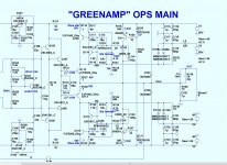
OPS is final ...
Unless Mr. Zan "can raise the Bar" ...
I went "original" -
Final .ASC , too.
I can't bit$h about 30ppm , even with the Schottkey switching.
Also is the Diode / Class H "handoff" in the second attachment.
REAL class H !!
Time for sprint layout (and component shopping).
OS
Unless Mr. Zan "can raise the Bar" ...
I went "original" -
Final .ASC , too.
I can't bit$h about 30ppm , even with the Schottkey switching.
Also is the Diode / Class H "handoff" in the second attachment.
REAL class H !!
Time for sprint layout (and component shopping).
OS
Attachments
Or do it like this...
Hi Damir, what's the latest news on this?
Finished?
One of the OnSemi models (unreleased as yet) does have quasi-saturation
Please update me when it's released, even more interested since it's Toni's data so at least that part should be correct.
If you search for flaws...
I wouldn't just point out flaws, I hope that's not all you expect from me.
For a start the EG parameter looks suspect.
This is an intrinsic property of the semiconductor, extremely unlikely to be far from the default (1.1).
This will mess up temperature variation.
Some of Cordell's models have the same problem, recently discussed and fixed in the software forum.
Unless Mr. Zan "can raise the Bar" ...
I am fairly sure I can, but not quickly, the weekend starts tonite!
The pic you attached has the lower V supply same as the upper 60 V.
Ok in the ASC.
Best wishes
David
Hi Damir, what's the latest news on this?
Finished?
Best wishes
David
I have PCBs ready, but still straggling with power supply. No point to use big transformer, and low voltage switching ps not easy to find in 6-7V range. Probably ones for LED, not sure if good enough?
Best regards
Damir
where are the multiple supplies or envelope tracking bucks with required coil.
the schematic looks like an odd 60v dual rail setup. this being the case, no power loss is eliminated by linear regulation of the 60v supplies to 30v supplies.
the schematic looks like an odd 60v dual rail setup. this being the case, no power loss is eliminated by linear regulation of the 60v supplies to 30v supplies.
Last edited:
Time for sprint layout (and component shopping).
V3, V4 are most likely 30 V 😉
For a start the EG parameter looks suspect.
This is an intrinsic property of the semiconductor, extremely unlikely to be far from the default (1.1).
Do you think EG is mistakenly used to fit Vbe vs Ic? I've noticed Irb tends to be in the microamp or nanoamp range, which would be consistent with an evolutionary solver disagreeing with Rb.
V3, V4 are most likely 30 V 😉
I just upped the inner rails to 60V without changing the schema. Set it back
to class H before I submitted it.
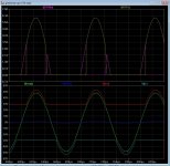
I "wrapped" this project around the known slewmaster OPS. So one can compare
the max 15ppm of the EF3 with the 30ppm of the class H.
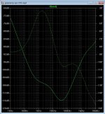
The trackers now don't switch at 20Khz (Below 1-top plot)
The schottkey's switchoff (D106) corresponds to the "glitch" at the VAS (R18).
The CFA is so sensitive it shows the diodes (and AB crossover). It also
corrects it to <30ppm 20khz .
I am hoping that the selection of this will help :
https://www.mouser.com/datasheet/2/196/Infineon-IDM10G120C5-DS-v02_00-EN-1226682.pdf
"NO forward or reverse recovery" SiC Schottky. It is that reverse recovery spike that is affecting my pursuit of near perfect performance.
Never used Silicon carbide , it can still work at 3-400C !!
https://www.mouser.com/datasheet/2/90/3m0065090d-838565.pdf
SiC output devices , too. Cool.
PS - new and better semi devices are becoming available , and cheaper. We better
learn when/how to use them.
OS
Attachments
Last edited:
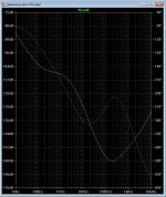
Why , voltage loss through the cap multipliers ?How about a low current full voltage separate ips power supply
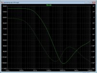
Or ,the multipliers themselves ? Even with this CFA, PSRR is -100db
Think about this ... between the multipliers and the class H , we lose 8 volts
output swing. Clipping starts at the IPS VAS. This is good , the output stage
never saturates.
And , with this amp .. neither does the VAS/IPS.
If you did have a separate IPS supply , the VAS would not clip first.
But , you still have the Class H trackers to limit the swing of the output stage.
It is best to leave it as it is - make dual mono analog 30V supplies , with a big
Connex 600W SMPS for the 60V rail (use for both channels).
30V supplies can be small 2-300VA ,not many amps up to 50v p-p .
In class H , the trackers act as series regulators. The output stage is
fully regulated in this instance .
Edit - ripple on the outer rails is almost at (PSRR) nonexistence.
OS
Attachments
Last edited:
Do you think EG is mistakenly used to fit Vbe vs Ic? I've noticed Irb tends to be in the microamp or nanoamp range, which would be consistent...
I must admit I've never bothered to work out exactly how these shonky values came to be.
I had noticed the shonky IRB value too (also RBM is impossibly low) so your idea seems plausible.
Some of Bob's faulty models also have the same combination of bad EG and too low RBM and IRB.
But some have only bad EG, probably just copied from model to model because people don't want to mess with parameters they don't understand.
So I'd default EG, set RBM to a physically reasonable value (about half RB) and then set IRB based on the datasheet (in the order of half the maximum current for the transistor)
Best wishes
David
Last edited:
The original KT-Cordell models have served many well here. Myself,
VZaudio , many others. Predictable end projects.
Is not Quasi saturation more is the low voltage/ switching domain ?
The 2sc3503 model definitely exhibits the same saturation in sim vs. scope.
I only had one IPS not predicted nearly perfectly by LT , the H-bridge.
That was way off thermally and in bandwidth ( RF amp 😕).
OS
- Status
- Not open for further replies.
- Home
- Amplifiers
- Solid State
- GreenAmp ++ modulated Class G output