What about the protection questions?
I've already replied. NO protection integrated on this board. You can either buy any other modules to do this.
You did say that the doubler supplies were on the pcb. Even if you did not mention the protections specifically, no commenting on them made me assume they were not included.
But that is not what I had asked. My question had been if you can add that additional filter Goldmund had included for oscillations on the protection you had proposed, based on the UPC1234, which I had uploaded.
Thanks!
But that is not what I had asked. My question had been if you can add that additional filter Goldmund had included for oscillations on the protection you had proposed, based on the UPC1234, which I had uploaded.
Thanks!
You did say that the doubler supplies were on the pcb. Even if you did not mention the protections specifically, no commenting on them made me assume they were not included.
But that is not what I had asked. My question had been if you can add that additional filter Goldmund had included for oscillations on the protection you had proposed, based on the UPC1234, which I had uploaded.
Thanks!
I have no intention to make this PCB. The filter part (I think you mean Zobel and Thiele network) is already on the board. Further, I have another PSU board with 1237 protection system, I think that would be enough.
And, you can buy 1237 boards from China easily.
The GM8-D remains a upgrade space for this (There are 4 additional screw holes). So it's not really a problem.
Since I have done protection boards for GM many times, I think the protection is not that important(?!)
Because these MOSFET have negtive temp co., and my topology won't cause any oscillation or instability in my experience.
Last edited:
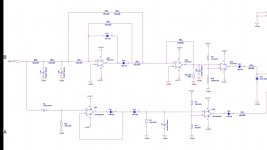
Here I found a Mimesis 27 preamp schematic.
Anybody built this preamp? Any pcd?
I have no intention to make this PCB. The filter part (I think you mean Zobel and Thiele network) is already on the board. Further, I have another PSU board with 1237 protection system, I think that would be enough.
And, you can buy 1237 boards from China easily.
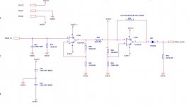
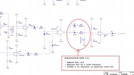
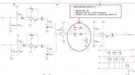
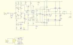
This is the oscillation filter Goldmund put on their power supply.
Attachments

Agreed, I won't buy eBay-GM things.
As I know, these eBay things are related to "DIYSONG MP-150", a mimesis29-based project from Taiwan.
DIY Research >> MP150後級擴大機組裝說明
Then, numerous clones were noted on Taobao/AliExpress/eBay. They use 2SK1058/J162 or even BJTs.
As I said before, GM with 2SK1058/J162 is not as good as Exicons and genuine Hitachi, but much more cheaper.
Even 2SC5200/A1943 was also noticed from these kits.
The Chinese got intelligence from Taiwan, and made many variants.
There are also some Chinese/Vietnamese guy aiming at higher class models, like Telos 250 and above. They have there own clones, which is different from the above I mentioned.
Are you talking us bad?
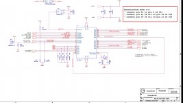
I have full original the service manual, include schematic from GM.
Some people on this forum have received original manual detailed from me, included JOB4, TL600, TL5000.
We are sure to building this Amp, instead use the junk schematic on the Internet.
Last edited:
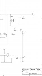
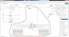
On TL600 with Over Current, HF Detector, DC Detector and Mute 😀This is the oscillation filter Goldmund put on their power supply.
Attachments

Last edited:
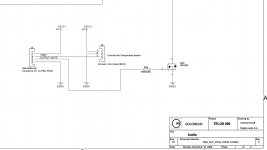
This is Digital Detector on TL600.Sorry, I don't know what you mean.
Pls check your inbox messenger to received high resolution.
Attachments

Last edited:
That is extremely complicated.
I was talking about the filter used on the Mimesis 9 protection, which also provided for high frequency oscillation.
I was talking about the filter used on the Mimesis 9 protection, which also provided for high frequency oscillation.
That is extremely complicated.
I was talking about the filter used on the Mimesis 9 protection, which also provided for high frequency oscillation.
You can stop comment to other schematic at here 😀
optimum idle current?
Depends on your taste. I'd recommend several ten mA, say 20mA.
What is that for? Input, VAS, drivers? The MOSFETs should be more like 100mA per pair to clear the crossover distortion. Some people and manufacturers run them lower, 80mA or 60mA to save heat and therefore use cheaper heat sinks. Some people run them at higher current.
You could try various current and hear if you can discern any difference with lower or higher current.
You could try various current and hear if you can discern any difference with lower or higher current.
It was originally set at 350mA, yes, 0.35A. It was set for first 30 watts classA. Even I have big heatsink on it, it was just freaking hot.
I set 50mA per output transistor. Should be close to optimum.
I set 50mA per output transistor. Should be close to optimum.
I though some of you could simulate the circuit and plot the distortion over idle current.
I do not have such capability.
I do not have such capability.
- Home
- Amplifiers
- Solid State
- Goldmund Wiki and build 2017