I though some of you could simulate the circuit and plot the distortion over idle current.
I do not have such capability.
I have plenty of sim files, wait for my result🙂
Correct me if there's more to it but:
Feed a sine wave signal in, look at the output on the oscilloscope. Turn the bias down until crossover distortion shows. Measure the bias current.
Feed a sine wave signal in, look at the output on the oscilloscope. Turn the bias down until crossover distortion shows. Measure the bias current.
This is very low distortion design, do you think you can spot change in distortion between 0.003 and 0.0026 % on oscilloscope?
I have three oscilloscopes and watching sine wave told me nothing. Can you spot 1% second harmonic distortion just watchin sine wave?
Spectrum analyzer is the only way to go.
Perform your studies, repot back.
I have three oscilloscopes and watching sine wave told me nothing. Can you spot 1% second harmonic distortion just watchin sine wave?
Spectrum analyzer is the only way to go.
Perform your studies, repot back.
Last edited:
That's not cross over distortion which is what I'm talking about just now 🙂
Cross over distortion - Google Search
Scroll down and bit and there are some nice tutorial videos that show in pictures what I'm saying here. 🙂
Transistors (and MOSFETs) are not linear for the 0.7 volts or so between off and on. To overcome that problem, turning them on by about 0.7V means they never go onto that area. That's Class AB and is what the idle bias current is for.
You should see the crossover distortion as you turn your bias down toward zero. Then you can discern how much bias is the minimum you need for your particular amplifier 🙂
You can also try a lot more bias current and hear if there is any improvement over the minimum.
Last edited:
You're correct. Low bias is not recommended for LMOS due crossover distortion issue.
Please see AN-1645 of Texas Instruments to see THD change from low to high bias.
Please see AN-1645 of Texas Instruments to see THD change from low to high bias.
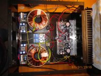
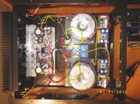
I run my main mosfets at 100-125ma per mosfet..
Hand made all...
Hand made all...
Attachments

Last edited:
Very interesting data sheet. Thanks. http://www.ti.com/lit/an/snaa045a/snaa045a.pdf
Seems like a lot of difference between the different manufacturers MOSFETs. Not that that matters any more as only the Exicon's are available: Lateral MOSFETs | Profusion
Maybe should run some extra bias!
Seems like a lot of difference between the different manufacturers MOSFETs. Not that that matters any more as only the Exicon's are available: Lateral MOSFETs | Profusion
Maybe should run some extra bias!
Last edited:
600 to 750mA. That's a lot of heat for that L bracket to move to the main heat sink. Have you measured the °C of the MOSFET cases?100-125ma per mosfet
I recently measured some TO3's, 126mA quiescent per pair, and they were on what looks like thicker Alu, part of the main heat sink, not a bracket, and they were about 60°C at idle. Probably starting to increase their Ron.
Ian
if i remember well i mesure them at summer on case about 55 C - 60 C , my L bracket it is 5mm...
I will measure it again and inform you....
if i remember well i mesure them at summer on case about 55 C - 60 C , my L bracket it is 5mm...
I will measure it again and inform you....
Last edited:
adason
I know this is an old post, however; I have recently purchased the same Goldmund Gm29 kit as you, and was wondering if you have settled on a good idle bias, and if you made any modifications to your boards, EX: changed caps or input transistors to 2sk170?
If so, was there a noticeable improvement over the original?
Hi all,
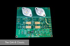
Finally, the two series of my 8th generation GM have already arrived.
I call them GM8-Classic and Deluxe.
The GM8-Classic:
- 1 pair TO-3 MOSFET
- mini size
- gold-plated
- no exchangeable module
- no PSU
The GM8-Deluxe:
- 2 pairs of TO-247 MOSFET.
- Gold-plated with double thick copper.
- Equipped with interchangeable module sockets.
- integrated with rectifier/filtering.
- Voltage doubler for front-end supply.
Hi Erikovsky, what rail voltages for these amps? I assume around 100watts? Which model are they based on? Do you provide any build instructions and BOM?
Hi Luke,
Thanks for the question. I run them by ~60VDC per rail, 1~2 pair. About output, yes, around 100W, I am using bookshelf speaker so no need for higher power.
The GM8-Deluxe with interchangeable module makes everything interesting. I am going to build a module with 2SK170 pair, without damaging the mother board!
Is anyone interested in Group-Buy of GM8-Deluxe?
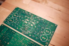
I can make some very good quality Gold-Plated, 2Oz-Copper, 2mm-thick PCBs.😉
Thanks for the question. I run them by ~60VDC per rail, 1~2 pair. About output, yes, around 100W, I am using bookshelf speaker so no need for higher power.
The GM8-Deluxe with interchangeable module makes everything interesting. I am going to build a module with 2SK170 pair, without damaging the mother board!
Is anyone interested in Group-Buy of GM8-Deluxe?
I can make some very good quality Gold-Plated, 2Oz-Copper, 2mm-thick PCBs.😉
Attachments
What a pathetic design. Just a bit of "spin" . nothing interesting.
Never to promote any other designs , but the goldmund is easily beat
for either distortion products or native lowest thd. EASILY.
Not even a good 90's design.
OMG !!
OS
Never to promote any other designs , but the goldmund is easily beat
for either distortion products or native lowest thd. EASILY.
Not even a good 90's design.
OMG !!
OS
What a pathetic design. Just a bit of "spin" . nothing interesting.
Never to promote any other designs , but the goldmund is easily beat
for either distortion products or native lowest thd. EASILY.
Not even a good 90's design.
OMG !!
OS
There are so many Goldmund fans for reasons. Have ever heard Goldmund?
Does insult other people's design make your design better?
but the goldmund is easily beat
for either distortion products or native lowest thd. EASILY.
Distortion is not even important anymore. There's a reason why I asked a LATFET design. Look at Dadod's 200W CFA thread. It started out as Latfet amp but 'ended up' with IRFP. For a reason.
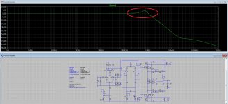
My simulation above uses 2N5566 model, if i use high gain JFET models such as K170 to replace, the oscillation even more worse.
On another hands, DIYers in my country who have tried to clone Goldmund next gen amps. Based on that information of next gen amps, i also tried to sims. Result: still oscillating.
How, how they fix problem?! probably GM sells their amps with oscillation. Is there any mystery?
On another hands, DIYers in my country who have tried to clone Goldmund next gen amps. Based on that information of next gen amps, i also tried to sims. Result: still oscillating.
How, how they fix problem?! probably GM sells their amps with oscillation. Is there any mystery?
Use source resistors on the Jfet to match the transconductance of the original FETs.
The simulation models for the MPSAxx transistors may not be accurate. That or they may be from a different manufacturer than what Goldmund uses. As an aside the MPSA42/92 are IIRC terrible transistors for this application when it comes to specs.
What you are seeing in the simulation is not oscillation, it is peaking/ringing. I don't know whether this is present on an actual Goldmund. Oscillation would be a constant sustained ring. Overshoot does not guarantee that an amp will ever oscillate in operation but peaking does increase the likelihood that it will oscillate during transients.
- Home
- Amplifiers
- Solid State
- Goldmund Wiki and build 2017