Hi all,
Got some valuable files.
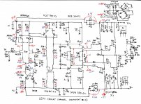
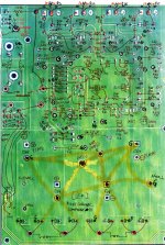
Seems to be G-390D schematic and copper bottom scan.
Got some valuable files.
Seems to be G-390D schematic and copper bottom scan.
Attachments
Last edited:
Hi erikovsky, i have ordered g29 goldmund clone from ebay. It has k30a pair on input. I do have some original k170 toshibas, i can replace with. Would this improve performance?
Still waiting for heatsinks, so not tried and listen to it yet.
I got schematics, do you want me to post it here and for your wiki?
What idle current is recommended for the outputs?
Still waiting for heatsinks, so not tried and listen to it yet.
I got schematics, do you want me to post it here and for your wiki?
What idle current is recommended for the outputs?
quite a few people asked me for the ebay link
here it is
One pair Assembled HM3S High Bias Class AB Amplifier base GOLDMUND GM29 120W *2 | eBay
here it is
One pair Assembled HM3S High Bias Class AB Amplifier base GOLDMUND GM29 120W *2 | eBay
Hi erikovsky, i have ordered g29 goldmund clone from ebay. It has k30a pair on input. I do have some original k170 toshibas, i can replace with. Would this improve performance?
Still waiting for heatsinks, so not tried and listen to it yet.
I got schematics, do you want me to post it here and for your wiki?
What idle current is recommended for the outputs?
Sure, why not share schematic with us here? 🙂
As for Idle, my simulation says under genuine parameter, it should be less than 1mA.
according to carlmart the amp is no good, it has high distortion
Agreed, I won't buy eBay-GM things.
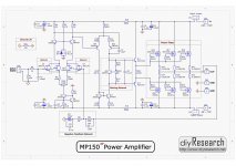
As I know, these eBay things are related to "DIYSONG MP-150", a mimesis29-based project from Taiwan.
DIY Research >> MP150後級擴大機組裝說明
Then, numerous clones were noted on Taobao/AliExpress/eBay. They use 2SK1058/J162 or even BJTs.
As I said before, GM with 2SK1058/J162 is not as good as Exicons and genuine Hitachi, but much more cheaper.
Even 2SC5200/A1943 was also noticed from these kits.
The Chinese got intelligence from Taiwan, and made many variants.
There are also some Chinese/Vietnamese guy aiming at higher class models, like Telos 250 and above. They have there own clones, which is different from the above I mentioned.
Attachments
Sure, why not share schematic with us here? 🙂
As for Idle, my simulation says under genuine parameter, it should be less than 1mA.
Are you serious or just joking? It's high bias...it heats like hell in idle.
I have only temporary heatsinks on it, so not fully running it. At normal listening level it measures 0.026% distortion, purely second harmonic. No third detected. I have limited measuring capability, only rightmark audio and soundblater card.
No mods yet.
No mods yet.
Are you serious or just joking? It's high bias...it heats like hell in idle.
Changing R16 value from 470 to 680 makes huge difference.
I think 10~100mA is OK for this amp, but uA works just fine also (in SIM).
Anybody knows exact value of idle current?
Attachments
Last edited:
according to carlmart the amp is no good, it has high distortion
Sorry, but I didn't say it's no good. I just said the THD was high on the simulation I did.
The purpose of a simulation is just that: to try to predict how things might be.
Even the original Goldmund does have high THD on the simulation. Perhaps someone could get it to simulate with lower THD.
But that doesn't mean the amp is bad, as many people had built it or bought the original Goldmund, and find it awesome.
But that doesn't mean the amp is bad, as many people had built it or bought the original Goldmund, and find it awesome.
Yes, Goldmund is definitely AWESOME!
That's why I am so crazy about it!
I can upload the sims I did, both for the original GM and the GM29 clone.
From the sims I did, the best in THD was the one Keantoken had modified on a DIYAudio thread.
From the sims I did, the best in THD was the one Keantoken had modified on a DIYAudio thread.
So, would it be fine if I used 2SK30A (matched pair) in the input, instead of 2N5565? And 2N5551 in place of BC182B? Any suggestion on japanese 2S to replace the latter?
Last edited:
My simulation files and technical analises
I got schematic from Carlos and did some simulations and analysed what was wrong.
Carlos can share my points of view and simulation with all of you.
Ronaldo
I got schematic from Carlos and did some simulations and analysed what was wrong.
Carlos can share my points of view and simulation with all of you.
Ronaldo
Ronaldo did the investigation, and got what is wrong in that kit and is missing (or faulty) on the MP150.
The 33p capacitors should be a tenth of that: 3.3p. Slightly less than what the original Goldmund used.
As I know DIYAudio policy does not allow showing anything from eBay, I will not upload that amp simulations. Correct me if I'm wrong.
In any case, it's interesting to know (and see on the simulation) how those feedback caps play such an important job.
Ronaldo did the investigation, and got what is wrong in that kit and is missing (or faulty) on the MP150.
The 33p capacitors should be a tenth of that: 3.3p. Slightly less than what the original Goldmund used.
As I know DIYAudio policy does not allow showing anything from eBay, I will not upload that amp simulations. Correct me if I'm wrong.
In any case, it's interesting to know (and see on the simulation) how those feedback caps play such an important job.
Hey Carlmart,
Can we share simulation files privately? Though I have my own, but I would be interested to sim other version.
Thanks.
Hey Carlmart,
Can we share simulation files privately? Though I have my own, but I would be interested to sim other version.
Yes, of course. PM me your e-mail and also tell me what you want.
Yesterday I also did some tests with the original Goldmund schematic, and those I can upload here.
Carlos
Just measured the idle current on the amp from ebay, it was close to 200mA. No wonder it was running hot. I lowered it to 50mA. Still sounds good to me. Still waiting for bigger heat sink.
Just measured the idle current on the amp from ebay, it was close to 200mA. No wonder it was running hot. I lowered it to 50mA. Still sounds good to me. Still waiting for bigger heat sink.
Two things the simulation shows that are interesting:
1) You should add the 12v zener + 1N41448 string between the driver's bases, as shown in the original GM schematic.
2) You might try lowering the 33p capacitors values to 4.7p or 3.3p, also as the original schematic. You should check with a scope for the exact value for this one.
Both improve THD considerably.
- Home
- Amplifiers
- Solid State
- Goldmund Wiki and build 2017