I don't think I need the transformer, I can hang my Kmultipliers off my 54V toroid and that should be good enough, what say you?
BTW, after learning much these last months, I'm working on the Kshunt again. I'm looking at a lower noise version with less drift, using the BZX55 low-noise Zener.
- keantoken
BTW, after learning much these last months, I'm working on the Kshunt again. I'm looking at a lower noise version with less drift, using the BZX55 low-noise Zener.
- keantoken
Last edited:
LED 11 and 12 are reversed.
Not only that, they won't last longer than a blink at that current. You'll want to bump those 1k resistors up to 10k or so.
I just put together a topology folks, NOTHING is in stone, just a overall layout...😛
But keep coming I am headed for results and I am laying out a board now...😉
This is fun whatever the direction😱
But keep coming I am headed for results and I am laying out a board now...😉
This is fun whatever the direction😱
Perusing the datasheet, the LM317/337 is startlingly inferior.
Zout at 1MHz for the 317 is 1R, but the same for both my Kmultiplier and Kshunt is 60mR. It redeems itself in the audio spectrum and in the PSRR numbers, as long as you don't forget Cadj. For this reason I want to avoid the LM317.
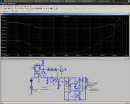
How about this? I've discovered the perfect solution! It should beat the LM317 in speed, ripple rejection, and noise. Now the shunt is rock solid against varying mains voltage and interference. Unfortunately, it uses a lot of parts... Yellow trace is output impedance (flat to 1MHz!). Orange trace is ripple rejection, far beyond what an LM317 is capable of.
- keantoken
Zout at 1MHz for the 317 is 1R, but the same for both my Kmultiplier and Kshunt is 60mR. It redeems itself in the audio spectrum and in the PSRR numbers, as long as you don't forget Cadj. For this reason I want to avoid the LM317.
How about this? I've discovered the perfect solution! It should beat the LM317 in speed, ripple rejection, and noise. Now the shunt is rock solid against varying mains voltage and interference. Unfortunately, it uses a lot of parts... Yellow trace is output impedance (flat to 1MHz!). Orange trace is ripple rejection, far beyond what an LM317 is capable of.
- keantoken
Attachments
Hi Kean,
I am not sure why you want a stable impedance up to MHz, are we not working at DC?, Who cares if the impedance is 1 Ohm at 1 MHz.
I am not sure why you want a stable impedance up to MHz, are we not working at DC?, Who cares if the impedance is 1 Ohm at 1 MHz.
Who cares if the impedance is 1 Ohm at 1 MHz.
Surely, Nico, you can hear the difference...?
😉
Surely, Nico, you can hear the difference...?
😉
I am listening intensely, and... yes! yes I hear it 1 MHz, very faint though 😀
Salas might be able to comment about that
Don't know from design stage, I always try to think about some traits after I have built a circuit and subjectively experienced it also. In general when they are wide in bandwidth and over engineered for Zo they tend to sound kinda distinctly open and relaxed from experience.
P.S. I would think that strong aces up this amp's sleeve to make a difference beyond Kean's rework of the main CCT will be TMC and his supplies.
Just thought I'd suggest it, you know. Don't saw my head off with a breadknife, staple my internal organs to trees and send pictures to my dearest kin, okay?
Sheesh.
Even if the LM317 might be the better option for Zout in the audio band, the shunt should be better for noise, no? Let's err on the side of novelty for once...
- keantoken
Sheesh.
Even if the LM317 might be the better option for Zout in the audio band, the shunt should be better for noise, no? Let's err on the side of novelty for once...
- keantoken
I suppose the same argument could be applied to designing an amplifier capable of 1 MHz.
That is another good point. Although I like to design amplifiers that work in the 100's of KHz, for what reason I am not exactly sure, am wondering if this is really that important. If you replace your speaker with an antenna, do you need a broadcasting licence?😱
Don't know from design stage, I always try to think about some traits after I have built a circuit and subjectively experienced it also. In general when they are wide in bandwidth and over engineered for Zo they tend to sound kinda distinctly open and relaxed from experience.
P.S. I would think that strong aces up this amp's sleeve to make a difference beyond Kean's rework of the main CCT will be TMC and his supplies.
Yes, Yes, Yes, and all of that with an engineered ground plane once the kinks and rough edges are eliminated 🙂 This should be a sweet amp in anyone's book.
I remember some thirty years or more ago working for an military RF crowd, I used two 500 watt DC - 500kHz modulators as audio amps. If my memory does me justice they sounded pretty okay, but did not look like hi-fi.
Let's err on the side of novelty for once...
- keantoken
Semis are not that expensive these days, if its stable and does not hurt anything, why not integrate? Its a hobby, you build to satisfy curiosity, not on economy brief. I mean why get down to this amp if it wasn't just curiosity in the first place and not build an Edmond Stuart's that would make more of a cutting edge sense? Amps will come many, each one's a toy, humans play to learn. But that's only my POV.
Keantoken:
Please give me some more info on your circuit, I am not able to discern exactly how to implement it with the output of the transformer I mentioned earlier. I have lots of trans so parts count is not a problem....
Plus and minus Please
Please give me some more info on your circuit, I am not able to discern exactly how to implement it with the output of the transformer I mentioned earlier. I have lots of trans so parts count is not a problem....
Plus and minus Please
Last edited:
Salas, I think that you read the essense in DIY audio, playing and forever changing, whether it is an improvement who can tell, it makes one happy. What makes it even more obsessive is the advent of simulators, it is just another game, one designed for the simulation junkies.
Indeed, if it was a design say for the army, the mind frame would be build to sense, less is more, make it as proof as an AK-47.
Kean, it is simple, just add two more power supplies (transformers, diode bridge, caps etc) that will be added on top of the main rails. These transformers are small 100mA or so 9V types you buy for a dime a dozen. Smoothing caps need not be large value, calculate for the load that you are drawing, and besides the caps only need to be 16V not 130V, because these power supplies are added to the rails.
Do you follow or do you want a picture?
Do you follow or do you want a picture?
- Home
- Amplifiers
- Solid State
- Goldmund Mods, Improvements, Stability