I'm referencing the SOA chart for the outputs. 100mS is 10Hz, which is below worst-case for audio.
- keantoken
- keantoken
OK, I just raised the issue of power dissipation to make sure your considered it. Off hand I don't know the equation for power loss in the class B amplifier, but I'm sure google can help you. I didn't intend to be difficult or negative.
What are the power transistors?
What are the power transistors?
IMHO stick with the original premise here, using the Goldmund as a starting point.
Modify, improve and stabilize it. At least at its original output level. Incorporating at least 4 pairs for the output. IF you need some output devices, just say so and I bet somebody will ship them to your door tomorrow, that includes me. A schemo is just a ask away if you will furnish the details.
Modify, improve and stabilize it. At least at its original output level. Incorporating at least 4 pairs for the output. IF you need some output devices, just say so and I bet somebody will ship them to your door tomorrow, that includes me. A schemo is just a ask away if you will furnish the details.
The idea was that I would develop the high-voltage version first and then downgrade, but using 80V rails for these devices looks insane to me (either no one pointed it out or I seriously lost the memo). That's a good thing in one way though, because my test transformer is 54V.
- keantoken
I mentioned it a couple of times, in nagy's original thread (maybe here too I don't remember now) but it fell on deaf ears.
2SK1058 Datasheet pdf - Silicon N-Channel MOS FET - Hitachi Semiconductor
Your help is appreciated.
I already paid for 2 pairs from TechDIY, and I'm wondering why they're not here now along with the other precious things I bought.
The original Goldmund used 70V rails I think, and relatively low filtering. Perhaps for the same reason as AndrewT's amp. My preference would be a stiffer supply, to worry less about PSU-related distortions.
For 8 ohm speakers, my 54V toroid seem optimal. For 4ohm or lower which require more current and less voltage, lower rails are probably best.
As for the schematic, I'm still not entirely sure what I should do about the upper rails regulator. For now, I will probably use the CFP-multiplier below:
http://www.diyaudio.com/forums/powe...ntokens-cfp-cap-multiplier-3.html#post2376286
I've built and tested it, it is stable even into film caps, a feat that the best shunt regulators couldn't pull off.
Must sleep now,
- keantoken
So a STIFF plus and minus 70V rail is in order and the front end to support it with 4 pairs outputs😀 2sk1058 and its partner 2sj162🙄
DOES Anyone that think this is wrong direction to head?😉
I am going to start a schematic and I hope someone finishes one before I do as usual😛
DOES Anyone that think this is wrong direction to head?😉
I am going to start a schematic and I hope someone finishes one before I do as usual😛
4pair and +-70Vdc would be great for any 8ohm speaker.
I would need to check (all) the details, for 6ohm and 4ohm speakers.
I would need to check (all) the details, for 6ohm and 4ohm speakers.
keantoken,
formal education or not, in my book you are on the right path. keep focusing on what youbknow and the end result and all will be good.
this is precisely how i hoped this threaf wouod shape up. folks comong together to collaborate and share insights. you just continue to be the beacon and drive things along.
par
It's a mystery to me why everyone is so hot for this design (or any that uses these overpriced lateral MOSFETS) in the first place. The outputs cost twice as much as more suitable BJTs would.
Do you fellows really think that audio nirvana hides within the structure of these devices, waiting to be unleashed?
🙂
Do you fellows really think that audio nirvana hides within the structure of these devices, waiting to be unleashed?
🙂
Do you fellows really think that audio nirvana hides within the structure of these devices, waiting to be unleashed?
🙂
I think it might make sense to do a fine little 50watt
with a single pair outputs, and no device matching
but for high power ? no, doesnt really seem like a clever choise
mind you, this is an outsprung from skilled "marketing"
the awkward thing is, some good harted dissbelivers seems to still be stuck in the "scam"
but praise and promisses of "shiny gold" obviously makes people go crazy, and loose their head
I think its a paradox
but nothing wrong with "studying" the thing
but to be real
have anyone even heard anything that supports this "idea"
any measurements, anything substantial
or is it only based on heresay and "gold rush"
There are many amplifier designers that would use Laterals as their first choice for the improved performance that they give in Audio applications.
I think it is only price that prevents the Lateral taking over.
I suspect even BJT protagonists might change ship if Laterals were much cheaper.
I think it is only price that prevents the Lateral taking over.
I suspect even BJT protagonists might change ship if Laterals were much cheaper.
http://www.diyaudio.com/forums/soli...s-improvements-stability-104.html#post2379515
From Alex MM
Is everyone in agreement to this schematic BUT with 4 output pairs, TMC by OS and the shunt regulators that Keantoken designed?😀
From Alex MM
Is everyone in agreement to this schematic BUT with 4 output pairs, TMC by OS and the shunt regulators that Keantoken designed?😀
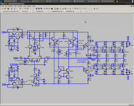
This is the most up-to-date schematic I have. There needs to be 4 output pairs, not 3.
I have been playing with parasitics and thermals lately, so I will simulate the amp again with a more realistic simulation. There may be a few more changes to make... After I do this I will update the schematic.
- keantoken
I have been playing with parasitics and thermals lately, so I will simulate the amp again with a more realistic simulation. There may be a few more changes to make... After I do this I will update the schematic.
- keantoken
Attachments
 so I certainly cross my fingers for success here
Well if and ONLY IF Alex MM will grace us with his superior Talent... I think he could eaisly modify the board he posted earlier to include all this... Where are you ALeX?
and combine the http://www.diyaudio.com/forums/powe...tokens-cfp-cap-multiplier-15.html#post2376286 with 4 outputs and TMC by OS
I have four pair of the same and I am ready today to etch some copper...
I am going to have to do a work around on the input FET pair, could not find um.
and combine the http://www.diyaudio.com/forums/powe...tokens-cfp-cap-multiplier-15.html#post2376286 with 4 outputs and TMC by OS
I have four pair of the same and I am ready today to etch some copper...
I am going to have to do a work around on the input FET pair, could not find um.
Here I am , please draw a nice , final schematic diagram wich contains all you mentioned TMC , etc, etc and I will make ,an decent schematic and PCB ofcourse with your help guys . 🙂 BTW ...Happy New Year !
Alex.
Alex.
Christmas came again a day or two later...
Keantoken, where are YOU...🙄
🙂🙂🙂THANKS so much ALEX🙂🙂🙂
Keantoken, where are YOU...🙄
We don't need a fancy schematic yet do we? Just something that will get us into the prototyping stage, right? I just don't want to annoy Alex with lots of last-minute changes delays.
IIRC there was a specific trafo setup so we could use small 9V transformers next to the power transformer to boost up some rails. I thought it was Nico or someone who suggested this. Does anyone have the schematics?
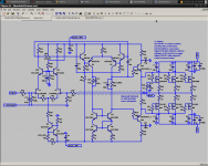
Here is an amp schematic with K-multipliers. This is very close to what I will end up with for my prototype, and what I would recommend for the TMC prototype.
- keantoken
IIRC there was a specific trafo setup so we could use small 9V transformers next to the power transformer to boost up some rails. I thought it was Nico or someone who suggested this. Does anyone have the schematics?
Here is an amp schematic with K-multipliers. This is very close to what I will end up with for my prototype, and what I would recommend for the TMC prototype.
- keantoken
Attachments
Keantoken:
I have 2, willing to share one, of the Hammond 162G120's
Hammond Mfg. - Power Transformer - (162 & 164 Series)
Do you want it?
I started this... All help accepted😀
I have 2, willing to share one, of the Hammond 162G120's
Hammond Mfg. - Power Transformer - (162 & 164 Series)
Do you want it?
I started this... All help accepted😀
Attachments
Last edited:
LED 11 and 12 are reversed.
At 50mA, a darlington won't do you any good. You can just use a singe KSC3503 in the place of T7 and T9. Or you can use a CFP with BC550 driving the KSC3503. In fact, why not replace T7 and T9 with the K-multuplier?
But are you sure about using the 317/337? They are slooooooooooooow and not low noise. The Kmultiplier is low noise and very fast, at the cost of lowish output impedance. The 317/337 would still be very useful as a preregulator.
- keantoken
- Home
- Amplifiers
- Solid State
- Goldmund Mods, Improvements, Stability