Hello everyone.
Yes, I have been away. It has taken nearly 30 minutes to read through these posts.
I have written up several posts, and in the end lost them all to stupid errors. Forum needs a "save draft" feature, because there are so many ways to delete your information online it's not funny.
Second, the image problem is a forum error. Before, the images weren't manipulated in any way after being uploaded. Now, there is a white border around them, and when maximized, pixel lines are deleted with no interpolation. It is very annoying.
Jam, I will not answer your questions regarding the drivers because this requires testing a prototype. I know that it would definitely reduce the slewrate, which was a criteria for the finished design.
About the outputs, I thought we had a max of 6 pairs, 4 pair default, and less than this optional.
Ostripper, there is no gain limit on the left half of the VAS. Without local limit on it there may be problems. Although oddly enough I never saw issues in my simulator. Without local limit the amp relies on the limit caused by the loading of the Cdom cap "multiplied" through the right VAS. Also, I think perhaps we should keep with the "no phase lead" criteria, it is one of the defining features of the Goldmund.
Andrew, simulation helps you get a grasp on the theory. In real life, you will never be able to directly observe some things. Only good mathematicians/theorists will be able to figure out things you could observe in simulation. This is why it is an invaluable tool for hands-on learners (although knowing the math is just as good). Even if the results are valid, you can see how multiple approaches affect the issue from multiple perspectives. This thoroughness is rare in real life. Even if the results are not valid, if you are a discerning observer you will come back with knowledge of cause and effect that will help once verified and adjusted for real life.
- keantoken
I can't disagree, you and ost have shown that competent use of a simulator brings forth learning, not just faster learning, but becoming aware of an influence that would otherwise not be observable without enormous research effort.............Andrew, simulation helps you get a grasp on the theory. In real life, you will never be able to directly observe some things. Only good mathematicians/theorists will be able to figure out things you could observe in simulation. This is why it is an invaluable tool for hands-on learners (although knowing the math is just as good). Even if the results are valid, you can see how multiple approaches affect the issue from multiple perspectives. This thoroughness is rare in real life. Even if the results are not valid, if you are a discerning observer you will come back with knowledge of cause and effect that will help once verified and adjusted for real life.
I am part of a real life example that appears to support your alternative learning method. But first I will state my stance. One must understand what you ask the simulator to predict and using that understanding determine if the predictions are anywhere close to the truth. If you can't check the validity of the answers coming from the model, one should not be relying on that model.
Now to my example.
I can draw (graphic calculation) and calculate (numbers) the angles that apply to independant car suspension. I can do this slowly and each "calculation" can take from 4hrs to 2days depending on accuracy required.
I came up with a way to program the extensive calculations into GW Basic. The computer, way before PCs were invented, could do the calculations in seconds. This allowed me to investigate various geometries hundreds of times faster than done manually. I discovered a property of roll-centres that is never discussed in the technical literature. It appears that those who know about this "property" realise it's importance to suspension design that they keep it as an "in house" secret.
The modeling allowed me to learn something new (to me).
Simulation works in helping to learn !..
NO !
Modeling and simulation allowed me to learn faster. I already knew how to do the calculations. I already knew how to build the geometry I wanted in my car. I already knew how to check that a model gave sensible predictions to the questions I asked. I wrote the software that created the model.
Some 23 years later I have still never seen mention of this suspension roll-centre property discussed or detailed in the technical press. I once saw the exact opposite proposed as a hypothesis. I wrote to the author, but he admitted to being a programmer, he knew nothing about suspension and as a result he did not understand what he was saying nor why it could be inverted to become true. I let that discussion lapse. Anyone who read his paper on computerised suspension calculation would be deceived by his opposite conclusion and be unaware of how to get stability into the handling of a car where the suspension is "moving" relative to the car and the road. I don't mind if that means I win competitions because my car is, or feels, more stable.
Last edited:
A little know fact is that digital computers ONLY know how to do one thing mathematically, and that is to ADD. Computers subtract, multiply and divide by ADDITION ONLY. It, the computer is a very fast adding machine. There is no subtraction command, or divide or multiply either.
That said, by themselves computer do not think they only do what they are told to do.
THE most successful use of computers is a combination of a human giving directions and setting limits, and with the computer rapidly performing calculations based on what the human dictates.
BUT in the words and deeds of Ray Kurzweil, we are at the dawning of the SINGULARITY, when the distinction between human thinking and the computers is blurred.
In other words computer can HELP analyze the circuit design but can not directly come up with it in the first place.
The computer today is a TOOL, tomorrow it might be death of us.
Dr. Theodore John "Ted" Kaczynski was not the entire fool the MSM portrayed him as.
So where are we?😀
Thanks🙂
Last edited:
By andrew T. - I can't disagree, you and ost have shown that competent use of a simulator brings forth learning, not just faster learning, but becoming aware of an influence that would otherwise not be observable without enormous research effort.
"Cause and effect" , especially with the .step command. I am a little weak in the math department , but my 12th grade eldest daughter helps me - she just uses paper ... no calc or PC. 😎
I must learn to calculate the poles and zeros. I know what they are and can see their "cause and effect" on the simulator , but I want the fishpole instead of the fish. Contrary to some opinions , this topology is very good and deserves hard work. It is consistently linear and even has the tendency to improve THD wise with higher frequencies , this explains it's Superior mid and HF reproduction. The ultimate learning tool is the one I will have on 12/8 ... the real thing with a few extra pads for the "magic".
I really appreciate all the good minds around here and this is why I feel the need to contribute. Keen , Andrew , MJL , Cordell , E stuart and a few who left us for the "other side" are notable in thier patience and teachings. Today is a special day , I thought last night I would not see this day , I rafted down the flooded river (below 1 - left a big sandbar) and nearly drowned . 🙁
 I guess some thrills have a price. The flooded main creek pix in my profile was tripled last night. 😱 I am SOOOO glad to be alive this morn.. 🙂🙂
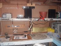
(Pix 2) is the lab I am devoting to make better amps for DIYA and of course myself (pix3) , I owe the community at least these things , if not more.
Thanks everybody!!OS
Attachments

Did you use the CRTs for buoyancy?
Good one.. 😀 I think they sink..😀
I should of thrown them in, they would of ended up in toxic Knoxville , just kiddin'.
OS
I rafted down the flooded river
Sometimes you eat the bar.
And sometimes the bar eats you.
YouTube - Deliverance - Banjo Duel
A little know fact is that digital computers ONLY know how to do one thing mathematically, and that is to ADD. Computers subtract, multiply and divide by ADDITION ONLY. It, the computer is a very fast adding machine. There is no subtraction command, or divide or multiply either.
Thanks🙂
hello?!!? there is olenty of instructions to do divisions multiply adds, subtract in the commnd set of a computer. there are circuits specialized in this and while generically you can make this point many, many instructions exists to implement the commands at the machine level.
x86 has add, div, idiv, sub, xor and + a whole slew of instructions far exeeding simple additions.
modern alu's are built with bitshifters and boolean logic much more than cmos addition.
power supply....power supply and grounding....are vital key elements.
ex.. how to prevent power supply sags between output devices...
A question could be....how to separate power ground from signal ground....is that better done before or after the front end regulators..?? is it done on the amplifier PCB or on the power supply PCB..??
ex.. how to prevent power supply sags between output devices...
A question could be....how to separate power ground from signal ground....is that better done before or after the front end regulators..?? is it done on the amplifier PCB or on the power supply PCB..??
hello?!!? there is olenty of instructions to do divisions multiply adds, subtract in the commnd set of a computer. there are circuits specialized in this and while generically you can make this point many, many instructions exists to implement the commands at the machine level.
x86 has add, div, idiv, sub, xor and + a whole slew of instructions far exeeding simple additions.
modern alu's are built with bitshifters and boolean logic much more than cmos addition.
EVERY single one of those use ADDITION as its root. At the register level there is only add or inversion of one bit to another.
It appears that those who know about this "property" realise it's importance to suspension design that they keep it as an "in house" secret.
Hi Andrew
Are you referring to adjusting the suspension geometry so that the roll centre does not move, or are you referring to adjusting the suspension geometry so that the roll centre moves in a desired fashion, or are you referring to adjusting the suspension geometry so that roll centre is in a desired position.
You got me curious.
Sorry to go off topic everyone.
Simulator guys lost a sense for reality and reject any good idea cause simulator ends with the result of + 0.01% distortions at 100 kHz. Nice theoretical discussions serves only for themselves with no use to improve the sound of an amp. To my opinion any promising idea must be practically checked by lots of listening tests and at the end of the day you pick the best sounding solution, not the one simulator suggest you with lower THD digits. I seriously doubt that any of you have real sound sistem to make an appropriate evaluations by listening. You just roll around few test instruments and PC simulation software and rely on the results as they actually mean better sound. Wrong! Tell you guys that's not the way making superb sounding amplifier. 
power supply....power supply and grounding....are vital key elements.
ex.. how to prevent power supply sags between output devices...
A question could be....how to separate power ground from signal ground....is that better done before or after the front end regulators..?? is it done on the amplifier PCB or on the power supply PCB..??
From what I can see , both the little goldmund (nimisis3) and the original goldmund, the secondary PS's are just additional windings on the same trafo sharing the same CT. This means the voltage stage sees the same ground reference as the output stage , ripple, switching pulses and all. On my split ground PS , I position a small inductor between my clean ground (Voltage stage) and my "dirty" OPS decoupling ground. I admit , I am only using a single supply , but the measured noise on the voltage stage ground is hard to detect with my scope. Going out further to the signal ground I use a 10R resistor and there is nothing 🙂 .
I would need to see what interactions there would be between 2 totally separate center taps on separate trafo's. Any ideas ??? I think I'll take a spin around the WWW to see what's up. 😀
This is a very important consideration , I have NO tolerance for hum and buzz , why would one with a modern amp ??
Simulator guys lost a sense for reality and reject any good idea cause simulator ends with the result of + 0.01% distortions at 100 kHz.
Here we go again with this "simulator guy" B__$ again. I build and share what I sim , and they come out pretty close to what is predicted. Some are worthy of keeping and refining and others are a waste of FR-4. That is why it is a prototype. My living room is the last "filter" after the simulation. I have spent hours swapping compensation caps independant of the simulator to see the effects.
As an example, I could do as my friend carlos (DX) does(did) and try every cap beween 22pF and 220pF as main compensation , going between an oscillator and smoked OP's to a sluggish "muddy" sounding sub amp. OR , I could define my unity gain point and degeneration and narrow my choices down to a smaller range ... much faster , and safer.
OS
Last edited:
ostripper..
So you have in realty 3 separate gnds...power ground..VAS ground and signal ground...
the reason for me asking is that i have a gut feel that the 10 ohm lift for the signal results in a sloppy ground that can be modulated by the driving signal....so for me the VAS and the signal gnd must be the same and supported by as much capacitance as absolutely possible...as I see capacitance.. it does not only give sufficient driving current.. but also secures a rigid and solid ground....which is just as important...hell maybe more important...
i believe careful implementation is the most important...when simulating... there's no such thing as dirty gnd...or capacitance and inductance in PCB traces...let alone spice models that are truly realistic....What I try to say is that we can continue fiddling with the minors and not solving the majors....Getting the basic conceptual structures of the amplifier right is the key to performance...not minute fractals of details in the schematic of ONE of the parts making the amplifier.
Last edited:
MiiB,
It is probably not appropriate to get into a discussion of the merits of simulation in this thread; however, it is my experience that simulation, coupled with a sound knowledge of electronics, can be extremely effective. In addition, you can add "ground" impedances in the simulation. This leads to some of the problems with simulation (or analysis) - you need to be able to figure out what the correct model is. What are the resistances and inductances of the traces? Do they matter? What about other coupling? The net-net is that the simulator will accurately solve the circuit you supply, but is that circuit a good representation of the actual circuit?
As long as I brought this up there are a couple of things that bug me. First, it seems that many folks think a model of a device (transistor) is absolutely correct, and neglect the fact that parameters vary widely. So worst case analysis is usually need (if the parameter variations matter), but it is normally neglected. Another issue is that all instances of a specific type device will be identical. This, for example, means that a LTP will have zero offset voltage. Of course, in reality this is nonsense. Likewise, all of the paralleled output devices will be identical and they will share the current perfectly. Again, nonsense. With a little work you can vary device parameters to eliminate this issue (yes, you do need to create separate models for each device) , but most people don't understand this enough to even worry about it.
Rick
EVERY single one of those use ADDITION as its root. At the register level there is only add or inversion of one bit to another.
peraps not at the register, i assume you mean in the alu. still, i think youre making a point which is useless. combinatorial silicon flanked by shifters and inverters is a bit more complex than an adder without any other circuitry.
and a subtraction operaion implemented as an addition without inverters and sfiters doesnt work. invert is more than addition.
anyway, i get your point and while i think its over emphaszed and desnt lead to any useful insights i understand wat youre going after.
The difference is I am talking about Machine Language and you are talking about Assembly Language which is based on machine language.
BUT we certainly will NOT belabor those points
Thanks🙂
BUT we certainly will NOT belabor those points
Thanks🙂
sawreyrw
This was not a discussion on the value of simulation.. but merely a statement on how far it will take you.. I find simulation amazingly good at to learn the secrets of the circuits..where to focus..if it behaves like this..or is the thermal compensation good, how solid does it seem, is it prone to oscillation. But this is just one step in the development..First is first...and I do believe one must settle on the basic concept first...."the building blocks" and the earthing strategy.. how are the parts connected and how do they interact....Then a there can be a sound foundation for the design of the blocks...
Trafo....1 pcs... voltage doubler..? or...?
power supply..... separate board...or..??
high voltage supply serial regulator or shunt.. separate board...or..??
earthing strategy... ground plane..Star or star on star....or..?
maybe this is considered trivial.. but never the less this is the foundation for the system..and without good wise decisions and good solutions, theres no chance that the result will be improvement over the original design..
In engineering FEA is considered a good and valid tool..that makes good engineers better..but makes poor engineers far more dangerous....!!!
there it is again.In engineering FEA is considered a good and valid tool..that makes good engineers better..but makes poor engineers far more dangerous....!!!
One must know what the software is doing and be able to check that the results/predictions of/to the operators questions are valid.
- Home
- Amplifiers
- Solid State
- Goldmund Mods, Improvements, Stability