Thanks.
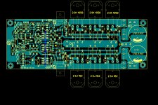
130kpixels and <24kB.
I call that quality and a success.
Can anyone explain why 1120 thumbnail (150x134) is more legible than 1112 thumbnail (150x135)?
130kpixels and <24kB.
I call that quality and a success.
Can anyone explain why 1120 thumbnail (150x134) is more legible than 1112 thumbnail (150x135)?
Last edited:
still,
there is still room for civility and respect. even on internet forums.
i think this post is disespectful of your fellow member and that the exact same point can be made using far more pleasant language.
there is still room for civility and respect. even on internet forums.
i think this post is disespectful of your fellow member and that the exact same point can be made using far more pleasant language.
Just to tell you to keep this thread going, I am looking for a 150 - 200 W per channel in 8ohm... This is looking good and I am willing to fund some of the development.
I also have a good source for transformers, hand made and reasonably priced.
I also have a good source for transformers, hand made and reasonably priced.
Can anyone explain why 1120 thumbnail (150x134) is more legible than 1112 thumbnail (150x135)?
I think you can probably answer that for yourself AndrewT.
Downsizing generally has decimation as the final step of the process. Any resizing involves at least one of interpolation and decimation, just like audio resampling. An unfortunate coincidence can result in loss of significant detail. A human could notice and tweak the outcome but there's been no human intervention in this case.
w
An unfortunate coincidence can result in loss of significant detail.
happens occationally, especially with paint drawings, it seems
Im sorry Kris, but please lets not start that
But you are right, some things are best kept seperated

But you are right, some things are best kept seperated

Mil Spec has nothing to do with the "Electrical Characteristic of an electronic part."
When I worked for National Semi there where NO difference in the parts we made for mil spec and your standard parts in the semiconductor manufacturing process. The ONLY difference was packaging and the products where TEMPERATURE tested. NOT electrically tested in any different way.
Mil Spec refers to the ability of the parts to be mechanical shaken and to with stand thermal shock and extremes i.e TEMPERATURE.
The parts are NOT different😛
I am sure other GM power amps are using ALL Mil Spec parts, transistors resistors, and Caps with FR-4 pcb with irradiation testing for good luck...
Last edited:
you may think differently
but I suggest you guys shake hands, and take care of your own
and maybe be happy there is anything to take care of at all
dont make it all a bloddy waste of time
and if you have to fight, go somewhere else to do it

but I suggest you guys shake hands, and take care of your own
and maybe be happy there is anything to take care of at all
dont make it all a bloddy waste of time
and if you have to fight, go somewhere else to do it

Kean has been absent for a while..................the questions about an extra pair of outputs and deleting the drivers has not been answered.
Jam
Jam
IF I can devise a easy way of implementing TMC I just might go on and build the board as is.
Maybe Alex will post the pcb layout.
I am going to wait for a while.
The power supply is my only holdup for real
Any body built anything yet?
Thanks
Maybe Alex will post the pcb layout.
I am going to wait for a while.
The power supply is my only holdup for real
Any body built anything yet?
Thanks
OK keantoken if you think 10-22 k VAS load would decrease performance significantly than maybe rather use this GND anchor which would do no harm to performance but only improve stability.😉
I believe Nico and did not add the cascode to the "back end" of the VAS. Not because he said so , I just noticed better transient stability without and a better upper harmonic FFT (or lack of - distortion wise). I do/will reference my beta enhancements to a real ground because of a "accident" on a blameless based beta enhancement prototype. The "anchor" ground , as you put it (cascode , both BE emitters)... will actually improve the VAS distortion wise at the expense of transient stability. On all the 2 previous genererations of this topology I've tried WITH the cascode , a small "whine" can be heard at the time of collapsing rails (shutdown). Without the cascode ... nothing ??
Addressing the "weaknesses" of the original goldmund really can't be done without actually building one. I set out to improve on one I know. the symasym. Brittners amp is so very similar to the goldmund I actually didn't need the original , I already have one (with BJT's of course).
1. With or without the comp. changes ,the sym/goldmund/ hitachi topology has a VAS current mirror that is "sloppy" , add a 3 or 4 transistor wilson CM and you halve the THD.
2. The goldmund and the sym have unconventional compensation schemes. The goldmund tries to scrape every last bit of speed by undercompensation and the sym just shunts it's way to glory (but sounds good). A honest improvement would be to increase loop gain which both keen's and my versions do (80+ db vs 50+ for the GM/sym). I went further and added the dreaded TMC to make better use of my extra gain. In NONE of my different compensations schemes have I had any outright oscillations or blowouts , just annoying errata as explained above or less than stellar soundstages.
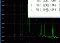
There are other enhancements in both device choices and general configuration that should come as standard , but the point is... it can be improved.. 🙂 (below) I know it is a crappy 🙄 173 PPM 1k/ 300+ @ 20k w/ stellar harmonics (FFT) ,but it is consistent up to 25khz and is very tame in any transient test. I could lessen input degeneration and get across- the -board 50ppm or less , but this is not as important as the FFT structure.
I can only wait until 12/8/10 to really audition it. (mouser order)
Oh , krisfr ... TMC has a "bug" with this type of topology and need a little extra compensation at the input cascode to eliminate the "TMC phase peak" at UG point which only occurs with this type amp. I solved it (pioneer mod) (below 2) , (should) work for keen's version as well.
OS
Attachments
Last edited:
Thanks OS, that was a VERY refreshing and informative post.
My dreams will be well intentioned tonight.
Attention, right Face. Forward...
My dreams will be well intentioned tonight.
Attention, right Face. Forward...

Thanks OS, that was a VERY refreshing and informative post.
My dreams will be well intentioned tonight.
Attention, right Face. Forward...
Yes , I had to get it right before I went to FR-4 . A combination of other works (ampslab/pioneer), the wonderful "cordell NFB" thread , and some personal experiance might just get me something in the end. Luckily , I just have to make a voltage amp board to "play out" my theories. 🙂
OS
Hi OS,
Refering to post #1133, you can use Miller cap on left leg of VAS(base Q7 to cocollector Q8) , it is simpler and it works.
dado
Refering to post #1133, you can use Miller cap on left leg of VAS(base Q7 to cocollector Q8) , it is simpler and it works.
dado
Hi OS,
Refering to post #1133, you can use Miller cap on left leg of VAS(base Q7 to cocollector Q8) , it is simpler and it works.
dado
Tried that , no effect on the phase , also tried 5pf lead comp. at GNFB , made the phase "hump" worse. What you suggest also affects TMC , partially negating the reduction of high order switching distortions that TMC usually reduces. I will ask the Masters on the cordell thread exactly what is happening with this compensation scheme in regards to this application. I know it works well , but I must know WHY.
This errata does not happen with conventional miller comp and does not happen with any blameless based amp , but it does with any vas based on a differential. Ampslab uses the RC , and pioneer uses it with the M-90 which drives a differential with a differential . plugged in 33R/6800p .. perfect closed loop gain bode. But I still must know why .. hopefully tommorrow. 😎
OS
OS
Because you're dealing with compensation on differential signal going to next differential stage. Compensation on common GND or rail would simply not affect both sides of diff signal. It has to be done this way I mean with RC filter, cause basically it is frequency dependent load and it also rightfully follows the rule that each stage of the amp has to be properly loaded. That's exactly what I was tried to elaborate with 10-22k load on VAS. Defenitely VAS is not properly loaded with output mosfets only and this would put it on the right track. Simple as that. 😉
thanks for giving me credit for something I do not know.I think you can probably answer that for yourself AndrewT.
Downsizing generally has decimation
Your Decimation explanation makes some sense to me.
So, thank you for taking the time to enlighten.
Last edited:
Hi,
there is real learning going on in this Forum.
The two Members that stand out as the most improved, in my view, are Ostripper and Keantoken.
Both have learned how to simulate and how simulation can improve understanding. That's not a method that I advocate, but it seems to have worked for them.
I see the day when these two will be the new generation of experts guiding this Forum along the smooth audio path.
- Home
- Amplifiers
- Solid State
- Goldmund Mods, Improvements, Stability


