keantoken,
Your schematics are very difficult to read. Can you make them a little larger without making them too large to post to the group? Also, deleting the grid would help.
Rick
Your schematics are very difficult to read. Can you make them a little larger without making them too large to post to the group? Also, deleting the grid would help.
Rick
I have a schematic to publish, but without complaining about it, no sooner than I finish getting it RIGHT, it changes. So I can if it is wanted or I will hold off until it settles down. I am just getting into the nicer schematic layout program, I will not name it now, and I should have the NEW schematic done in it, IF it does not change too much. The one I have is in KiCad, it is up to date NOT...
Kean let me know WHAT to do.
THANKS
Kean let me know WHAT to do.
THANKS

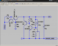
Here is the regulator schematic, pending tests.
A few component values might change, but I think the circuit is mostly frozen.
- keantoken
A few component values might change, but I think the circuit is mostly frozen.
- keantoken
Attachments
Last edited:
I will insert this into the NEW schematic.
Then I will gen a double sided plated thru hole star ground plane with and with out emitter resistors TO-3 TO-247 layout garantided 1000% ready to go to group buy, by tomorrow morning as soon as I fire up my heathkit Ipad oscope application.OK?
Then I will gen a double sided plated thru hole star ground plane with and with out emitter resistors TO-3 TO-247 layout garantided 1000% ready to go to group buy, by tomorrow morning as soon as I fire up my heathkit Ipad oscope application.OK?
Wait, one more thing.
The 90/80V rails were chosen to beat the 150W barrier. My thinking was that if we designed the higher power version first, we wouldn't have a chorus of "high power version?". Then the low power versions for the rest of us would be trivial to make.
Do we need an extra output pair for the high power version?
Other than this, there is little doubt in my mind we are ready.
- keantoken
keantoken,
Your schematics are much better since I "whined". Thank you.
I still don't buy the design of the shunt voltage regulator. Can you post the .asc file along with any necessary model files?
Rick
Your schematics are much better since I "whined". Thank you.
I still don't buy the design of the shunt voltage regulator. Can you post the .asc file along with any necessary model files?
Rick
Kean,
I think we need four pair of output devices for low Z loads or bridging applications.
Jam
I think we need four pair of output devices for low Z loads or bridging applications.
Jam
Kean,
I take that back, make that six pair, I just realized that the devices are only rated at seven amps.
Jam
I take that back, make that six pair, I just realized that the devices are only rated at seven amps.
Jam
Here is the regulator schematic, pending tests.
A few component values might change, but I think the circuit is mostly frozen.
- keantoken
R1 should be a 2k trimmer if it will test good and finally employ that reg. Each J201 will not be having the same Idss. There must be means to tune the voltage and match to the other channel.
Hi,
will J201 in that position work as intended?
The J201 is intended to act as a CCS to control the current through the Vref.
If the CCS current changes then Vref will change and the accuracy of regulation will be lost.
Can a J201 with a source resistor to trim Id work as a CCS when ~600mVds is available?
make that six pair, the devices are only rated at seven amps.
For 42A continuous or 42A peak ?
jacco,
..............yes, I own Soundlab electrostatics and I would probably run them bridged .😉
I agree that this might be overkill for most people, but I think four pairs is minimum for the rails involved.
Jam
..............yes, I own Soundlab electrostatics and I would probably run them bridged .😉
I agree that this might be overkill for most people, but I think four pairs is minimum for the rails involved.
Jam
Hi,
will J201 in that position work as intended?
The J201 is intended to act as a CCS to control the current through the Vref.
If the CCS current changes then Vref will change and the accuracy of regulation will be lost.
Can a J201 with a source resistor to trim Id work as a CCS when ~600mVds is available?
J201 will have good TC stability around 1K2 Rs and 200-250uA current. That with 430-450K Rd and a 2K trimmer to allow homing in 90V for different Idss J201's will stay half travel around the 1k mark. I have used one J201 when I tested Ikoflexer's v2n-5d and it worked as a CCS under a 2N5087's Vbe indeed. Had a couple left and Just checked them, they are 0.7mA and 0.8mA under a 9V battery and the first one I checked with 1.5V battery also, is very steady at 0.64mA. Idss-Vgs(off) from Vishay data sheet shows under -1V pinch off for under 1mA Idss samples indeed, and gives 201's max Idss as 1mA. Higher range should be 202 that shares the datasheet. Kean should test for his best drift given the CFP's Ib tempco etc. After finding stable drain current drift with the Rs trimmer he can designate exact Rd for 90V. Could be zero Rs even as best in a system of tempcos. Can't foretell. His CCT's values are preliminary he wrote.
Attachments
You do not have to FULLY populate the board.
I like to see as much as reasonable on the board, 5 is great but 6 is doable.
To each his own CHOICE...
With close to 100 volt rails Front and Back why NOT...
DIY is the name of the game.
Thanks, we just might meet the sorta imposed deadline of this week end to start laying out the boards.
Board topology? Double sided, Ground plane or STAR Ground plane or Chicken What the Hell.
- Home
- Amplifiers
- Solid State
- Goldmund Mods, Improvements, Stability