The one danger we face is that this whole project has been simulated to death. Simulation usually has nothing to do with reaility and is only a guide. Many a designer has found that if you live by the simulation you usually die by it.
Good design practice and experimentation, with a working circuit, should rule the day.
Jam
Good design practice and experimentation, with a working circuit, should rule the day.
Jam
The one danger we face is that this whole project has been simulated to death. Simulation usually has nothing to do with reaility and is only a guide. Many a designer has found that if you live by the simulation you usually die by it.
Good design practice and experimentation, with a working circuit, should rule the day.
Jam
Okay Lets Build some working circuits...Except for the output trans I am ready to go.I can get them in a day or two while I make the pcbs.
Guys, now this thread is buzzing and ideas are flowing. I congratulate you all for the work done in the last three pages. And you are right there is no need to use any of Nico's ideas they were meant for kick off and do something. You are doing a great job and it is looking extremely promising.
Baxiang, welcome to DIY.
I will disappear into the wood work and follow you guys progress with genuine interest.
Baxiang, welcome to DIY.
I will disappear into the wood work and follow you guys progress with genuine interest.
Guys the power supply is not that complex, look at #438, it consist of two mickey mouse 9V PCB mounted transformers that has its secondary connected to the main transformer secondary to get a supply of about 12 - 15 V higher than that supplying the power section in order to swing the mosfets closer to rails. 1VA will do.
1/3rd the price , in this case for 30$, we could go dual mono on a poor mans budget.
By Jam - The one danger we face is that this whole project has been simulated to death. Simulation usually has nothing to do with reaility and is only a guide. Many a designer has found that if you live by the simulation you usually die by it.
Good design practice and experimentation, with a working circuit, should rule the day.
In the case of the HV power supply , it might be advantageous to simulate the impedance and ripple rejection of a few different regulators.as far as simulation,I have found the opposite,the simulator has saved my A_$$ many a time, allowing for changes that would take 20 minutes to do on paper/DMM to take place in minutes.
OS
Guys the power supply is not that complex, look at #438, it consist of two mickey mouse 9V PCB mounted transformers that has its secondary connected to the main transformer secondary to get a supply of about 12 - 15 V higher than that supplying the power section in order to swing the mosfets closer to rails. 1VA will do.
Yet another option... 2 - 24V "micky mouse" trafos are cheap indeed. there is one plus to this arrangement , the higher rails would share the same CT/ ground reference as the main PS. couple this with a shunt regulator and we have a $20
"improvement".
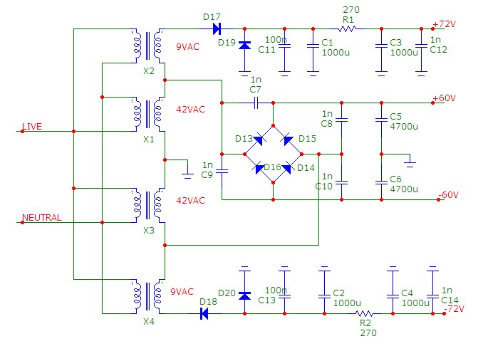
The one "negative" to this arrangement is that the primary trafo's load fluctuations would have to be filtered out by the regulators.
OS
Last edited:
OS,
Point taken.🙂
DC supply is looking good and fairly east to implement. If the main transformer is big enough, load fluctuations should not be too much of an issue.
Jam
Point taken.🙂
DC supply is looking good and fairly east to implement. If the main transformer is big enough, load fluctuations should not be too much of an issue.
Jam
Last edited:
HAMMOND|160E24|Bobbins Transformer | Newark.com
6.40 plus shipping
I like the independent ones better, not much diff in price.
6.40 plus shipping
I like the independent ones better, not much diff in price.
Last edited:
On the bright side , we actually have a working unregulated 70V supply and a durable softstart to use with this project. When we do decide on a regulated high voltage supply , I will be able to guinea pig it into my amp as I am already set up to accept independent voltage stage rails. (Vee2 and Vcc2 on PB250 BJT) . No more complaints about "just simulation" I do BOTH.
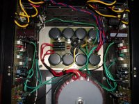
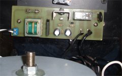
PS100 (50A bridge/ 65K uf - 100v) and SS1 (softstart 1 - 15 amp version) below.
OS
PS100 (50A bridge/ 65K uf - 100v) and SS1 (softstart 1 - 15 amp version) below.
OS
Attachments
I agree, let's keep the shunt regulator for the frontend - and hopefully a better performer than Nico's 1-transistor reg. I think we could come up with something good if we were to take something like Salas' reg that he posted here, and use a BJT output instead. I will post my thoughts later.
Baxiang, your input is valid and valued. I wasn't able to figure out what SR is. As far as operating points, everyone has their preferences for devices, Jfets and "sweet spots". It may be worthless to establish a "standard" in the engineering sense.
As far as the C6 thing... Let's try not to produce another outdated design, when so much progress has already been made. Options, for sure, but the final schematic should be something modern and effective, and hopefully a little novel. If it turns out an inferior amp sounds better, I don't mind. But we should also try to advance the art.
I must go to sleep again, so unfortunately I can only dream of the next few pages that will come in my absence.
- keantoken
I am a very “young” member,
Hello baxiang - and Welcome to diyAudio!!! 😀😀😀
You may be young - but you have some good insights and very good thinking. If you are just starting out with this audio stuff you have a great future ahead of you!
These guys have already been working at this for awhile - and are hot on the scent - so don't be concerned about the lack of replies - it isn't anything personal - they are just busy - and more than a little crazzzzzy!! 😉
I agree with Thomas, no one paid Bax much attention. If anything he indicated that this design is somewhat of a gamble, which I must admit I think is a fair way to say it. At this point we must build it, see what comes out in the wash, and improve the circuit.
I don't get the impression he is "young", but perhaps a more experienced designer, surprised by something he saw here, and wanting to tilt the board in a more organized direction (not unlike Nico!).
- keantoken
I don't get the impression he is "young", but perhaps a more experienced designer, surprised by something he saw here, and wanting to tilt the board in a more organized direction (not unlike Nico!).
- keantoken
Kean,
How does the open loop gain compare between the original design and yours with the beta multipliers on the VAS? I would think that if you want to keep it in the spirit of the original design that you should try to keep the loop parameters with regard to audio frequencies about the same, sure improve it for stability that is fine. I can see adding them also but that moves much further away from the original design IMO.
You could use more degeneration in the diff pair to bring the open loop gain back in line with the original.
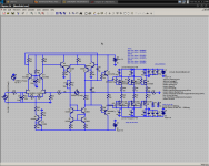
BTW, your schematics are a bit small and difficult for me at least to read.
How does the open loop gain compare between the original design and yours with the beta multipliers on the VAS? I would think that if you want to keep it in the spirit of the original design that you should try to keep the loop parameters with regard to audio frequencies about the same, sure improve it for stability that is fine. I can see adding them also but that moves much further away from the original design IMO.
You could use more degeneration in the diff pair to bring the open loop gain back in line with the original.
BTW, your schematics are a bit small and difficult for me at least to read.
Last edited:
Also, have you seen this, the Hafler XL280? It is a fully comp design - not suggesting to move this design in that direction but it might give you some ideas:
www.hafler.com/techsupport/pdf/XL-280_amp_man.pdf
The null circuit is also interesting.
www.hafler.com/techsupport/pdf/XL-280_amp_man.pdf
The null circuit is also interesting.
I think the idea of staying true to the original design went out the window several pages ago. If one wants to improve the stability of the original, they need only to increase the miller cap I believe.
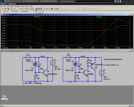
OLG for the new design is near 80db, for the original it was 53db. There are several ways to decrease it (my preference being a resistor across the bases of Q8 and Q7), and this goes in keeping with Jam's criteria for making open-loop BW high enough for audio before adding feedback. It could easily be option'd onto the PCB.
Attached is a better schematic. Krisfr, your NicoReg schematic is fine, but I want to wait for an improved design.
- keantoken
Attachments
kean,
I think you nailed it...........topology wise. I hope the other guys agree. I have very high expectations for this amp.😉
Jam
I think you nailed it...........topology wise. I hope the other guys agree. I have very high expectations for this amp.😉
Jam
Last edited:
The Nico Reg design is okay, I do not see how it works. I think that it needs to be changed. I only drew up what I was presented with. I don't think that the transistors are correct and the overall topology is correctly implemented.
BUT Please wait or give me some hints, clues or shoves in the right direction.
I would like to see some progress on the layout of the OPS. IF it is going to be separate.
Thanks
BUT Please wait or give me some hints, clues or shoves in the right direction.
I would like to see some progress on the layout of the OPS. IF it is going to be separate.
Thanks
jam:
i think you were earlier advocating to drive the mosfets direct from the vas.
are you ok with the followers to drive them now?
sorry, perhaps i missed a message or two.
i agree, this thing looks like it's cookin' pretty good now
mlloyd1
i think you were earlier advocating to drive the mosfets direct from the vas.
are you ok with the followers to drive them now?
sorry, perhaps i missed a message or two.
i agree, this thing looks like it's cookin' pretty good now
mlloyd1
Krisfr, usually when I see something as simple as Nico's shunt I consider it a conceptual schematic for learning. I wouldn't use it in real life when a few more components would greatly improve specs. I don't doubt it still sounds good, but I think we could do better.
For instance, look at the huge improvement from just adding one transistor. Zout goes from .6ohms to 54mohms, comparable to good electrolytics. How about a challenge? Who can get the biggest performance increase only by adding one transistor to this new arrangement?
- keantoken
For instance, look at the huge improvement from just adding one transistor. Zout goes from .6ohms to 54mohms, comparable to good electrolytics. How about a challenge? Who can get the biggest performance increase only by adding one transistor to this new arrangement?
- keantoken
Attachments
- Home
- Amplifiers
- Solid State
- Goldmund Mods, Improvements, Stability