Rico:
Can you post your regulator schematic that includes input power transformer, rectifiers, caps, transistors, diodes, Zeners, and resistors for both plus and minus. I want to make a schematic diagram for Alex to go by or maybe layout one too.
Thanks
Can you post your regulator schematic that includes input power transformer, rectifiers, caps, transistors, diodes, Zeners, and resistors for both plus and minus. I want to make a schematic diagram for Alex to go by or maybe layout one too.
Thanks
good work , Keen . I like "octoposts". We HAVE to agree on something. I personally like the beta enhancement , it reduces THD by a factor of X100. I went back to the original at Nico's request both to see how good that design could be "tweaked" and to see what all the "fuss" was about (goldmund thread / untested groupbuys). What I got was just about the same amp as the original plus the better wilson mirror on the VAS. I am satified with .01% and H2/3 dominant distortion. Adding the 2 beta enhancement trannies is interesting to me and I would add this to the voltage board as an OPTION (jumperable) ,... why not? Purist's obliviously would go with the groupbuy and build something fully untested , I am not that dumb. 😱 This is why the separate voltage stage with all the OPTIONS is the only way.
Bandwidth - I KNOW my input filter restricts BW. when I stated over 500K BW.. that was without any cap !!!
I was wondering whether someone would notice my omission of the basestoppers ... you did. I did this for the sake of the transient tests. In my exploration with OPS stability , (trouble with triples) leaving them out sometimes will be the factor that will "make or break" the stability of the OPS.
Below is the simple goldmund (goodmund) LT file which is set to 100w/10khz (.02%) with the new 2sk389 fet's and 2SK/J LFET OP models. as far as C6 (yammer , yammer) #1 . it is included in EVERY other commercial design with a similar topology (Why ???😕 ). I have found you can omit it with NO effect on the REAL amp (supersym 1). just another OPTION. (leave it out,dang!!)
PS.. Goodman device models are in included "mongrelmodels.txt" Also , consider the "ease of construction" factor. The original is a "nobrainer" , good for an easy , flawless build. (my supersym worked first time, 2mv offset - ran it for 15 months afterwards)
OS
Attachments
Last edited:
Umm... As far as I can figure out, the logic here goes something like:... as far as C6 (yammer , yammer) #1 . it is included in EVERY other commercial design with a similar topology (Why ???😕 ). I have found you can omit it with NO effect on the REAL amp (supersym 1). just another OPTION. (leave it out,dang!!) ...
A) The Goldmund does not have a cap there.
B) Adding a cap there serves no purpose.
but C) We're going to put one there anyway because some other amp with a similar (but different) topology had a cap in a similar (but different) position.
Am I missing something here? I don't see how adding a random extra part that serves no purpose counts as an improvement.😕
Can't clearly read the schematic posted by Kean, but would a cap across the Emmiters of the drivers (in parallel with the resistor) be redundant?
Umm... As far as I can figure out, the logic here goes something like:
A) The Goldmund does not have a cap there.
B) Adding a cap there serves no purpose.
but C) We're going to put one there anyway because some other amp with a similar (but different) topology had a cap in a similar (but different) position.
Am I missing something here? I don't see how adding a random extra part that serves no purpose counts as an improvement.😕
As I said , leave it out ! I Have(had) the real amp ,It makes no difference. Not "some other amp" , but all of them.
 The goldmunds topology IS the original (hitachi's) and the exact same as at least 20 other commercial power amp schema's I have.
 What's different is Goldmund's compensation at the VAS. I will leave the extra pads for ALL the compensations , but I know from actually having this amp in my house for 15 months what comp. I will use. Who is to say , Goldmund ... a company that uses an outdated grounding strategy and sells overpriced amps , just added those 4 - 4.7pF caps to shunt the VAS as to prevent catastrophic oscillation ( a freakin' "bandaid"). Trust not the goldmund , a company founded by a snake-oil salesman marketer , not a designer.
PS , my personal choice is just 1 - 15-22pF silver mica for C7. Compensation is an "art"... 🙂
OS
I am a very “young” member, as I only registered yesterday when I stumble across this thread. I spent the whole day going through the entire thread, excited by the beginning, confused a bit in the middle, and was quite amused towards the end. Nonetheless, it’s great pleasure to learn from others. And some of you have great experiences and ideas.
Here I want to share some of my own after chewing through the thread from beginning to end. Hope it’s not too late.
Power amp topology, for the most part, is very similar to opamps, just on a different scale. The theories governing the basic behavior are the same. Some of the parameters mentioned here, SR, BW, operating current, …. are actually well understood in the opamp design trade. Therefore it’s less of a matter of guess work, and more a calculated effort. There’s a very good paper by Solomon, “The monolithic opamp, a tutorial study”, which has been a bible for many analog design students. There are plenty others too.
Understand that you guys are anxious to kick this off, hope I am not disrupting anything to chip in at the 11th hour.
1) Choice of input stage operating current is not arbitrary. I affects gm, which affects SR and BW. Selection of I should not be a function of what i/p device is chosen, but such decision can be taken into account.
2) LTP current source, CCS or R ? – the main difference technically speaking, is the output impedance. In R, the Ro is simply the resistive value, nothing more. Whereas in CCS, the equivalent Ro can be much higher. This is important for good CMRR, PSRR. Even if you have regulated supply, there's no substitute for the high Zo of a CCS. Personal preference is an entirely different matter.
3) Driver stage or no driver stage – every stage (device) adds its own character, in audiophile’s terms. From an engineering point of view, every stage adds its own phase shifts and distortion. If one can do without it, the better. A tradeoff analysis should be carried out here.
First, the key is to design the VAS stage to have sufficient drive current for the o/p devices. Analysis should be made to see if the available (VAS) drive current and the Cin of the output stage will constrain the SR;
Secondly, the high C-load in combination with the relatively high Ro of the VAS will cause a pole. Is this better or worse than having a driver stage with its own phase shift but lower Ro?
4) The next question of course is how many o/p devices to have. Here the main consideration should be the maximum output current, under the WC load. Then the designer should check to see how many devices is needed to satisfy the SOA requirement.
5) My opinion on paralleling devices – for output stage, it’s inevitable. Anytime you do that, it’s bound to compromise the “coherence” somewhat, as individual devices are simply individuals (not the same). This is analogous to paralleling 300B in a SE amp. You trade the magic for the power. Paralleling is also sometimes done on input stage, in the name of higher gm. But this is usually a poor excuse.
6) Vreg for power amp, especially the output stage, as elaborated by many before us, is a lost cause. If one is still compelled to be adventurous, by all means.
7) Lastly, most power amps have at best, BW of a few hundred KHz, with PBW somewhat lower. This seems fine on the surface. What’s not looked at closely is the phase shift that accompanies this (limited) BW. My speculation is that a linear or 0 phase shift is a prerequisite for outstanding imaging.
8) On simulation– Simulation is a great tool, if you know (exactly) what you are doing.
9) Stability - The best way to check the stability of a design is to put it in follower mode (gain=+1) and force a suitable square wave on it. Any overshoot or more than 10%, much less ringing, points to marginality or stability problem. Repeat the test the different amplitude and loads. Contrary to intuition, high gm on the input stage is bad for SR and stability. This is where JFET comes in handy. Tweaking input stage gm is an effective means of dealing with stability besides compensation C.
10) Choice of parts – while different transistor types (part#) do make a difference, they are not going to affect the general operation that much, as long as the differences are not heaven and earth. For example, you would never put a TO220 type in the input stage, would you? There is no need to be overly concerned about the specific part for a specific location. One can always substitute the preferred type after a design is proven.
11) Cap voltage rating – as a good design measure, don’t forget that your incoming AC voltage can fluctuate too. You’ll need a 10% margin min.
Finally, there can still be limitless variations and tradeoffs. That’s where the designer comes in and makes his/her own imprint.
Cheers,
Baxiang:
I worked with Jim Solomon in the Linear IC Dept. of National in the early 70's, I learned a lot from him. He was against using vertical transistors in any audio IC design, but was forced to anyway.
I worked with Jim Solomon in the Linear IC Dept. of National in the early 70's, I learned a lot from him. He was against using vertical transistors in any audio IC design, but was forced to anyway.
Looks and sounds good to me, I was going to try and use KiCad to go from schematic to pcb just for grins. I seem to pick schematics that others have done and make mine look like I am wasting my time. Luck of the draw I guess.
I will copy and try to use one of the suggested transformers from eairlier in the thread, IF no one beats me to it.
I get anxious and just want to do something sometimes.
See, just my luck, I did not notice that your pdf included a pcb layout until I went to print it.
Thanks
I will copy and try to use one of the suggested transformers from eairlier in the thread, IF no one beats me to it.
I get anxious and just want to do something sometimes.
See, just my luck, I did not notice that your pdf included a pcb layout until I went to print it.
Thanks
Last edited:
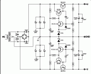
If anyone knows where to get a 60-0-60Vac secondary trafo , please inform.
On nico's ELD PS , I am putting together the sim now , be patient.
If... in the case an easy to source trafo CAN'T be found , a large doubler will have to be added to get our 80 volts.
OS
On nico's ELD PS , I am putting together the sim now , be patient.
If... in the case an easy to source trafo CAN'T be found , a large doubler will have to be added to get our 80 volts.
OS
If anyone knows where to get a 60-0-60Vac secondary trafo , please inform.
On nico's ELD PS , I am putting together the sim now , be patient.
If... in the case an easy to source trafo CAN'T be found , a large doubler will have to be added to get our 80 volts.
OS
What VA ?
http://www.plitron.com/standard-toroidal-transformers/power-transformers/north-american-117-v60-hz/
Last edited:
Guys,
What happned to the shunt regulator? A shunt usually sounds far better than a linear regulator. We seem to be straying from what was initially proposed, and taking a step backwards.
Jam
What happned to the shunt regulator? A shunt usually sounds far better than a linear regulator. We seem to be straying from what was initially proposed, and taking a step backwards.
Jam
I suggest that you simulate these regulators with small and equal input and output capacitors to see which one provides the lowest output impedance vs. frequency. Might also want to look at line and load transients for obvious reasons. I'm not expecting the best results here.
Definitely bigger than that hammond. 20va or bigger ,PCB mount is OK, each voltage stage will draw @ 20ma max. I measured my REAL working voltage stages - 16mA V+ and 19mA V- goodmund is biased at the same 6.5mA VAS , should have similar current requirement.
Wait ...philtron has just the one .... 30VA Power Transformer
An externally hosted image should be here but it was not working when we last tested it.
30VA/ 250mA/ 120V CT will give 88V rails , enough to negotiate the losses of Nico's "shuntaplyer" regulator circuit. 😎😎
PB , we don't have to use Nico's .. we have the whole salas thread , and a million other shunt's out there. i was just doing the preliminary and sourcing a trafo. Me and Keen will sim the "bejeezes" out of the best contenders.
OS
Last edited:
- Home
- Amplifiers
- Solid State
- Goldmund Mods, Improvements, Stability