I got bored.
There will be no outcome going on like this. Every time something is mentioned... Yeah, lets do this; Yeah, lets turn it on its head; Yeah, lets...
What exactly have we got here. Basically nothing. It was improving and stabilize. I would have thought that the thread will be something like this. Let us agree the circuit seems unstable when loaded with 10uF. Okay what are your solutions. The THD is to high lets agree on 10% what are the possible solutions and how does this impact on other areas.
It is going around in circles, not a single issue has been properly resolved it is called grabbing in the dark. Improving is a very nebulous concept, improving what, how.
A simulator is a tool for an engineer who already knows the outcome but uses it to very quickly confirm or disprove suspicions. However, enthusiasts spend hours trying to improve 0.00002% THD into 0.000019% THD with a simulator, or trying to improve stability in a circuit that already is stable in practice.
As I have indicated in an earlier thread, if Goldmund was that unstable and burning speakers and amps, they will not sell, but the do.
Good luck guys.
Cheers
Nico
Nico , the only real way to know ANY of this is to build the dang thing. Even on the other thread no one has built ANY thing. ALL "puffery"... "Best" ..hummmpff  . All that posting , all that work... DX has it right, before you make boards or "groupbuys", build it. I know there will be a half dozen revisions on the groupbuy board. 🙁 Also , they are putting the AC right on the main board , different layout, different OP devices , everything. I can almost guarantee that the clone will not sound anything like the original. 30$ input pair's GEEEZ.
OS
. All that posting , all that work... DX has it right, before you make boards or "groupbuys", build it. I know there will be a half dozen revisions on the groupbuy board. 🙁 Also , they are putting the AC right on the main board , different layout, different OP devices , everything. I can almost guarantee that the clone will not sound anything like the original. 30$ input pair's GEEEZ. OS
Last edited:
I must agree with Nico...there must be decisions made....And only one can do that
Fix and lock the Frontend..and then the second pair...
decide if the LAT's will be driven directly or through a set of drivers...(would clearly prefer the first).. then after topology had been made clear...select the devices...taking into account what is the current needs for driving the next stage
then find the operating conditions...how much current is needed to drive the next stage with good margin.. and what is the sweet spot for the selected devices..
Then look for the finer details such at the different resistor for N and P devices ect ect...instabilities...and decoupling..
Then it will be possible to go to the layout...where the most important will be grounding and feedback path...
I'am sure once the concept is locked.. this will bloom to life again...
Last edited:
Practical issue, drivers enable distance between the front end and the output stage.
Plus the drivers sit right at the gate resistors, with minimal trace length inbetween (in particular with itsy bitsy driver packages).
Spectral hasn't been using a 90 degree mounted piggy-back front end board for nothing.
Plus the drivers sit right at the gate resistors, with minimal trace length inbetween (in particular with itsy bitsy driver packages).
Spectral hasn't been using a 90 degree mounted piggy-back front end board for nothing.
For give me for plagiarizing any and all of this but I have gleaned this from several threads...
Whatever we do should include at least these as a foundation, please feel free to add anything to this list...
90 degree mounted piggy-back front end board
A full split .... separate voltage stage / current stage grounding and supplies with only regulated DC going anywhere near the input stage. Design for a +/- 100Volt front end rail system with 100 volt caps. Adjust down as needed to implement your design.
Use the plane for all power ground and use a separate star ground for all sensitive circuits. Don't mix.
NOW
We will not all agree on which topology to use, that will never happen...
SO...
Lets make a modular system...
So that what ever his or her choices for DEVICES is can be made.
OR
decide or 2 or 3 schematics and build your choice based on the modular PCB system.
Have a run off in a 6 to 12 month time frame where NO ONE will be happy...
So each of us state the criteria of this project and lets cut off debate in a week or so. run some sims and pray ALEX will give us his support. Just for grins say 6 Nov 2010 have a PCB board (s) system or no system started to be laid out. Fight, Learn and argue until then; after that join in or cut bait.
The Paralysis of Analysis is setting in.
This is and will be a great Thread, but is time for closure and put some hot heat to some copper boards, build, test, listen, and enjoy. Learn some more and do it one more time.
Gentlemen the smoking lamp is lit...Start your engines.
Krisfr,
It is ok, probably if the regulator is near the input stage(probably better) as long it is fed DC.
I am willing to agree to drivers, this should not be a dealbreaker.
Please start a master list so as we may add or delete items. I am sure we are pretty close to agreement..
Jam
It is ok, probably if the regulator is near the input stage(probably better) as long it is fed DC.
I am willing to agree to drivers, this should not be a dealbreaker.
Please start a master list so as we may add or delete items. I am sure we are pretty close to agreement..
Jam
What would be the form of the list?
Can it be on this thread?
Can we do just a back in power output device layout that would accommodate ANY To-247 devices and have or not have emitter resistors, etc...
Can we do just a Front end power supply board, everyone is saying it needs to be separate.
Can we do just a Back end power supply board system...
If we did this I think it would leave just the front end / Driver board...
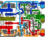
Open source, With a dedicated lateral board there is plenty of room for the cap multiplier or even a shunt reg. Look at my big BJT board (below) undo the jumpers , run a totally separate supply(Vcc2 - Vee2) .. jumper it , "clean up" a single supply. Some DIY'ers are strapped for cash , why not give them the option of "good for now, better later" (fully regulated separate supply).
I really am surprised modular has not caught on at DIYA. With either a BJT or MOSFET current stage , you just agree on a topology (EF2 ..etc.) and design. One could even "universalize" making a BJT/Vfet/Lfet creation ... GDS - BCE ... even allow the drivers to be left out with an optional Vbe for the VFET/BJT option.
With a prototype voltage stage , there will be many revisions. It is so much easier to revise a 10-20$ voltage board than to tear up a complete amp with every new idea. There is no performance compromise with separates, as well.
90% of your investment is in the PS/heatsinks and output stage. lock that down , go from there.
OS
Attachments
Guys, guys, Just a few posts and it is back to can we, should we, blah, blah.... Let us just switch our simulators off and and look at the greater picture and ask ourselves, what are we doing on this thread?
Our objective was lets fix up the Goldmund, (we did not even know what was wrong) being unstable was hearsay, or did someones simulator predict this. Now it became lets make the best sounding amplifier and everybody jumps into the pot all throwing in ideas of what he perceives is going to be a great sounding amplifier.
If you have never designed and built a working amplifier who is to tell what will make it sound the best, or even half good. The simulator?
No disrespect intended to anyone, but one cannot make a statement that this simulates better then it should sound better. It is not realistic.
There is no way under the sun that you will progress from a simulation to a finished product, heck then everyone will be building perfect amplifiers by next week-end.
I want to make a statement and you guys may or may not agree with, but a simulator has become an audio enthusiast's toy to play with and pass time, and you get addicted to it like any computer game that is it.
Any product starts life with a set of objectives like what is the power requirement, what is the load, what is the input signal, how do I amplify the signal without introducing artifacts. There are a lot more spurious stuff than harmonics, which should be the least of the problem at least you know what causes them.
The first thing most do is start with a differential amplifier, why? It is easy you can throw almost any component value at it and it somehow works. You can complicate it to the nth degree. You can feed back the mess that is at the output and through some magic it fixes it.
MiiB said something in a previous thread that was absolutely valid and I do not think anyone stopped and thought about it. Why use a constant current generator in stead of a single resistor if we already have a constant voltage. A constant current is derived from a constant voltage and resistor, simple and MiiB's logic is absolutely on target.
But the problem is everyone is too busy simulating some or other thing in order to demonstrate his findings in the next post, having no idea whether it is an improvement or even appropriate, what effect does it have on perceived sound.
That is what this is all about the perception of how something reproduces music, not whether it is a CCS, a bootstrap, a long tail pair, a VAS running at 1 or 13 mA, it is only about how it sounds, not how complex can be made or how smart I am or what I have read.
This is the reason for wanting to turn the brakes on and ask STOP, reevaluate and redefine the objectives and kick of from there.
The particular topology was that used by Goldmund, myself and many others, this topology is neither unique nor special, it is favored by some because of the perceived results they obtained and enjoyment derived from the sound, nothing else.
One can calculate every component value using on a piece of paper without the need of a simulator. You then BUILD your prototype and use basic instruments such as an oscilloscope and voltmeter to see if it behaves.
You can then use a simulator to see how it could perform in the perfect world and try and optimize your actual design, but you already know the practical result.
Most simulators uses pure resistors, pure capacitors, semiconductors that have a fixed set of parameters that is where, typical?
The whole design is at the same temperature, the battery source has zero impedance, it can supply a zillion amps instantaneously, what does this help?
How many of you chaps that are providing advice has actually built one of your own designs and can with great confidence say this design of mine actually sounds perfect? Better than the Goldmund or Niam or whatever.
I was around before simulators, before personal computers, before stereo, before TV and before transistors became the order of the day.
Cheers
Nico
OS:
You are making WAY too much sense..
So here are the GROUND rules.. no pun intended....
Agree on three areas
1 Output power supply board
2 Front end power supply board
3 Power output transistor board for what ever flavor device you like
4 An enlarged "Goldmund" type input and VAS board that can be plugged in and modified to your hearts desire, or your EARS desires...
observing the GROUND rules along the way.
A - If you have never designed and built a working amplifier who is to tell what will make it sound the best, or even half good. The simulator?
B - No disrespect intended to anyone, but one cannot make a statement that this simulates better then it should sound better. It is not realistic.
C - There is no way under the sun that you will progress from a simulation to a finished product, heck then everyone will be building perfect amplifiers by next week-end.
D - I want to make a statement and you guys may or may not agree with, but a simulator has become an audio enthusiast's toy to play with and pass time, and you get addicted to it like any computer game that is it.
E - Any product starts life with a set of objectives like what is the power requirement, what is the load, what is the input signal, how do I amplify the signal without introducing artifacts. There are a lot more spurious stuff than harmonics, which should be the least of the problem at least you know what causes them.
F-The first thing most do is start with a differential amplifier, why? It is easy you can throw almost any component value at it and it somehow works. You can complicate it to the nth degree. You can feed back the mess that is at the output and through some magic it fixes it.
G-MiiB said something in a previous thread that was absolutely valid and I do not think anyone stopped and thought about it. Why use a constant current generator in stead of a single resistor if we already have a constant voltage. A constant current is derived from a constant voltage and resistor, simple and MiiB's logic is absolutely on target.
H-But the problem is everyone is too busy simulating some or other thing in order to demonstrate his findings in the next post, having no idea whether it is an improvement or even appropriate, what effect does it have on perceived sound.
I-That is what this is all about the perception of how something reproduces music, not whether it is a CCS, a bootstrap, a long tail pair, a VAS running at 1 or 13 mA, it is only about how it sounds, not how complex can be made or how smart I am or what I have read.
J-The particular topology was that used by Goldmund, myself and many others, this topology is neither unique nor special, it is favored by some because of the perceived results they obtained and enjoyment derived from the sound, nothing else.
K-One can calculate every component value using on a piece of paper without the need of a simulator. You then BUILD your prototype and use basic instruments such as an oscilloscope and voltmeter to see if it behaves.
L-How many of you chaps that are providing advice has actually built one of your own designs and can with great confidence say this design of mine actually sounds perfect? Better than the Goldmund or Niam or whatever.
M-I was around before simulators, before personal computers, before stereo, before TV and before transistors became the order of the day.
Cheers
Nico
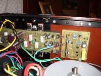
I have great respect for you , your designs , etc. .. but some of us are also realistic. Look below(attachment) , I have plugged a half dozen designs into "it".. all worked , none oscillated or burned up , some sounded better than others. ALL sounded better than any OEM receiver I have ever repaired (100's of them). A 7000$ genesis sounded better than some of them but not all of them.
In response to your comments... (Anatech style)
A - there is a correlation between general FFT distortion components of a simulation and what the amp sounds like. Not always correct , but I have found the way a simulation (FFT) "plays out" at LF 1k and 10k will reflect the clarity and/or warmness (or shrillness) of a given amp , especially when driven hard.
B- I am in total agreement , Carlos's (DX) ES with bootstapped current source sound better than a strait "blameless" even as the blameless has 1/10th the distortion.
C- You don't mean the "other thread" ,do you ??? They can't even get the grounding right. 😱
D- More of a tool , like a DMM. Change the VAS current , check how much this will require a change in your Vbe , go to the actual amp... make those same changes .... REAL CLOSE.
E- absolutely !!
F/G- Simple is better. I agree we can use a resistor to replace an active CCS. We are using regulated supplies for the voltage stage. Redundant. Some builders might not have a lot of $$$'s like you said you had and have to run off a single supply. an (optional-jumper-able) basic CCS might be a good choice.
H- most of what I simulate , I have built and heard. In fact , every "flavor" of the hitachi topology has actually been run in my living room. This is why I agree that the simulator "lies" occasionally. 😀
I - correct .. it all ends in smoke
 or smiles. 🙂
L- I have , I'm on my "3'rd generation" of designs. sold all my old ones to friends and neighbors or gave them away to newer members. My GX and BX are better than any of my receivers and the GX approaches the overpriced stealth in "listenability" and totally kicks it's butt in headroom.
M - So was I , man. My father worked for picker X-ray and then General electric in Schenectady, NY. I had a prototype GE tube color TV set in 1965 to see one of the first color transmissions from WRGB. I knew exactly how a flyback tranny and horizontal deflection circuit worked at 7.
Nuff said.
Attachments
Nico,
I must be just a little younger than you are, because transistors were used in all new designs when I started engineering. My first employeer had wonderful analog computers, but there was no such thing as a digital circuit simulator. I assume you know the SR-71 Blackbird was designed in the '50s. It still amazes me that when the plane is on the ground it leaks fuel, but when it is flying it expands and no longer leaks. I'm sure they used fancy mechanical calculators to do the arithmetic, but there was not such thing as finite element programs, etc.
Recently a customer - a government guy - asked me if engineers today were better than they were years ago. I almost punched him, but my answer was, no, but they can look at more alternatives and do certain analyses faster than in the past. However, garbage in - garbage out still applies.
On area where I don't fully agree with you is the use of circuit simulators. While I don't think you can completely design an audio amplifier with only a simulator, they are excellent "circuit solvers". They will provide correct results for any circuit you simulate. The problem is that you are not really simulating the real circuit - you are simulating what you think the circuit is. One of the biggest problems is component models are often incorrect or incomplete and don't represent reality. In addition, parasatic components and model tolerances are often overlooked.
Rick
I agree , it's all in the models. the old MPSA92/42's in LT's library wil simulate perfectly , never stick and rarely oscillate. The fairchild models will do all those things AND do them about at the point where the real creatures from mouser will. Same with simulators , I have microcap and LT .. they agree. Multisim , however , gives "best case" simulations and will simulate a circuit that will crash and burn on LT... go figure , it does have a "fancypants GUI - worthless.Nico,
I must be just a little younger than you are, because transistors were used in all new designs when I started engineering. My first employeer had wonderful analog computers, but there was no such thing as a digital circuit simulator. I assume you know the SR-71 Blackbird was designed in the '50s. It still amazes me that when the plane is on the ground it leaks fuel, but when it is flying it expands and no longer leaks. I'm sure they used fancy mechanical calculators to do the arithmetic, but there was not such thing as finite element programs, etc.
Recently a customer - a government guy - asked me if engineers today were better than they were years ago. I almost punched him, but my answer was, no, but they can look at more alternatives and do certain analyses faster than in the past. However, garbage in - garbage out still applies.
On area where I don't fully agree with you is the use of circuit simulators. While I don't think you can completely design an audio amplifier with only a simulator, they are excellent "circuit solvers". They will provide correct results for any circuit you simulate. The problem is that you are not really simulating the real circuit - you are simulating what you think the circuit is. One of the biggest problems is component models are often incorrect or incomplete and don't represent reality. In addition, parasatic components and model tolerances are often overlooked.
Rick
OS
OS
Lets make a modular system...
OS has this😀
He has an amp for every day of the week😱
I'm jealous, waiting when he will have some boards available.
OS you said it:
Multisim , however , gives "best case" simulations and will simulate a circuit that will crash and burn on LT... go figure , it does have a "fancypants GUI - worthless
Guys, I was nit-picking and got you all fired up and ready. NOW can we start looking at what we want to achieve? I am still part of this thread as much as anyone else and I am really interested in the outcome, else I would not spend so much time on it.
Has anyone have the Goldmund as it appears on a simulator. I have but I use MicroCAP, most of you use LT spice so we are not quite enterchangeable. I vote we use what most have available.
The entering comment was that it had stability issues, what were they? Lets first see them and then agree on what we see.
OS kan you do that?
Believe me I also get hooked on sims, but I brush my teeth in between.
OS Put the plot so we can all discuss the same problem. I don't want to go to Keans next observation else if will become entangled. The I dea is know what you have.
What I meant earlier that if you havent built and characterised what you simmed then you have no idea what causes one to sound good and another bad since both are variables.
What I meant earlier that if you havent built and characterised what you simmed then you have no idea what causes one to sound good and another bad since both are variables.
We should do the 90% first. Agree on grounding , the output section and power supplies. The fine tuning of the input/voltage stage last. Look at the glass as half full.
We agree on a separate power supply for the voltage stage. I feel this should be both backwards and forward compatible. If the builder only has 1 PS , he should still be able to operate the amp(w/ multiplier - good). If he is more endowed with resources , he should be able to go "anal" (higher voltage regulated supply + cap mult. , all the way - best). My example on the PB250 BJT board is "doable".
Most builders like the horizontal right angle way to implement the main amp board , like Alex mm's in the main goldmund thread. This can be ported to what I mentioned above easily with the cap mults. onboard and a jumper/ 2- fastons for external power supplies.
With a horizontal board , the separate input/ voltage stage can be positioned at a right angle from the main board. connections from the main board will be heavy pins and the euroconnectors will screw on to these. Goldmund modularized the cascode /input stage just to make the amp proprietary , so why can't we do this to make the amp more DIY "friendly".
Concerning the input/voltage stage , having a hard to find $30 dualFET as it's "core" is discouraging. The rest of the circuit with the MPSA92/94's is alright. I KNOW it will work , it is nothing special. The goldmund clones that are out there simply "upped" the Miller to 27-33pF. We have to choose components that people can afford and source.
Within a design group , would not these 3 sections of the amp be delegated to the most capable specialists ?? ...power , OPS and Voltage stage , maybe even a "layout master" (alex MM - definitely).
These are just suggestions as they relate to this amp and how to make it more accessible to the greatest number of hobbyists while retaining "near perfection". Goldmund seemed to focus more on esoteric philosophies than the actual core functions.
Edit: Another VERY valuable point to make is that without using the original TO-3 hitachi's or having them to compare against we really are designing a different amp. An EXACT clone of the goldmund circuit would sound and perform differently with newer laterals. A simulator CAN NOT predict this.
OS
Last edited:
Are you guys simulating a good time?
Attachments

- Home
- Amplifiers
- Solid State
- Goldmund Mods, Improvements, Stability