Guys,
Consider this, a current source can be a current limiter, unlike a resistor. If we up the current in the differential we can achieve the same thing and maintain all the benefits of a current source, which are considerable. More second harmonic distortion does not make a better amp enen though initially it might sound more pleasing.
Jam

in what way does the bootstrap outperform the CCS. What were the design objectives against which performance was measured. I cannot even figure out what is being simulated, let alone compare to see how and why there is such a discrepency in preformance, what performance?
My personal feeling is this thread will soon just die, instead of going forward it goes backward a few steps, then everything starts again. Why don't we place the circuit right side up it outperforms up side down.
Get some direction guys and come to a definitive conclusion. The guys next door came and see what we are talking about and already implemented it on the PCB.
Get some direction guys and come to a definitive conclusion. The guys next door came and see what we are talking about and already implemented it on the PCB.
The AC current of the tail is measured, and the lower wins. That is what was plotted
- keantoken
- keantoken
Why does the lower one win. Make it zero then it wins hands down. Why is a lower tail current important. For extended bandwidth and low distortion you need a high tail current. So I take it that you run the diff pair at nano amps instead of several milli amps. Can you tell me why?
Page 43 was the last time we had some show interest here, it just seems to go in any direction like a chicken that lost its head.
Nico, sure I could breeze through this and try to keep up with the other guys. Maybe a few guys would stop by and say "hey, that looks nice!". But, as it turns out, letting the idea wash in brain fluids for a little more time doesn't hurt. We are taking this carefully. Almost. Can we get a prototype please of this schematic? Any takers?
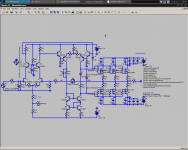
The circuit can be scaled down, as follows:
1: Adjust R6 and R7 to keep <2mA through Q8 and Q7.
2: Nevermind, keep tail current at 2mA, if you want to change it then ask.
3: Normally in the Goldmund the Jfets are at about 30V. This can be adjusted by changing R35.
Nico, the bootstrap performs better than the CCS, if you use precision resistors in the feedback and bootstrap networks. Some would prefer it.
I think you're right, maybe I suck as a project director.
- keantoken
Attachments
Last edited:
Nico, I'm not sure what you mean about changing LTP current. In both CCS and bootstrap simulations, CCS current was almost exactly 2mA.
- keantoken
- keantoken
It doesn't have to be MY schematic, it can be anyone's. The point is to modify it with the ideas put forth and see what is practical.
Unless we get a prototype and decide which is the best, we might as well all build our own separate amps with our own custom mods.
Hell, what if someone constructed a prototype, and we sent it around in the mail? Then we'd each have an opportunity to mess with it and decide which mods we liked best.
- keantoken
Kean,
I don't think 2ml is enough for fet differentials. Why don't you up it to 4ml and see. I think we re making a big mistake removing thr current source as Nico says and at this point would probably hurt this thread.Also the current source as impledmented can be vastly improved quite simply.
I think we should go back to Krsfr's circuit and decide drivers or no drivers but does not matt much if we design the board with drivers as they can be bypassed if necessary.
Jam
Last edited:
hey , I'm no idiot. I know even my J201's are most linear @ 3+ MA! since I port from BJT designs (I'm poor ,too)😱, I have to adjust to the "fet world"..
I have lost interest in this design , there are too many other better ones out there. I have NEVER built a fully comp design ... must do that for november.
Carry on , you guys can do it!! 🙂
OS
I have lost interest in this design , there are too many other better ones out there. I have NEVER built a fully comp design ... must do that for november.
Carry on , you guys can do it!! 🙂
OS
How about a dead bug style ground plane prototype? Then it could be freeform, and have something to brace against during shipping.
Jam, if that's what it takes, I'll bring back the CCS. However, the bootstrap if used with precision resistors is more than adequate, and quite possibly better than a CCS, especially for a high-speed amp.
What Jfets should I use? I'll try MiiB's suggestion for the SK170's, 6mA 12V.
- keantoken
Jam, if that's what it takes, I'll bring back the CCS. However, the bootstrap if used with precision resistors is more than adequate, and quite possibly better than a CCS, especially for a high-speed amp.
What Jfets should I use? I'll try MiiB's suggestion for the SK170's, 6mA 12V.
- keantoken
Kean,
I would use the 2sk170's at 6ml I have used as much as 8 cascoded at between 10 to 15v.
Jam
Nico where are you?🙂
I would use the 2sk170's at 6ml I have used as much as 8 cascoded at between 10 to 15v.
Jam
Nico where are you?🙂
Last edited:
OS,
Now you are talking. At some point we should do a full comp. thread and compare voltage feedbacki and current feedback versions.
Jam
Now you are talking. At some point we should do a full comp. thread and compare voltage feedbacki and current feedback versions.
Jam
OS, can you point me to one of the best?
Thanks,
- keantoken
"Best" is both objective and subjective , just like the original goldmund thread. Not to sidetrack this excellent discussion , but for "speed" (slew) and stability , I believe this is not it. The original topology (hitachi) was just good , the symasym was just a "stroke of luck" as the interaction between 2n5551's and shunt compensation made for a wonderful sound. Your "blameless" I gave you is among the "best" .. I believe It would match this one sound wise and even exceed it in THD. The hawksford I have now is by far the most seemless performer , even beating the symasym in vocals/ highs. The bass is better , too. Go look on my thread , it's different but might be the "best" (what a stupid word) 😀 Why do you think i go through so many amps .. "best" is hard to discern.
OS
Or 2 in parallel like on J. curls preamps. Maybe even a FET CFP ??? 11/10 I buy 25 J201's to play with... FET world , here I come. 🙂Kean,
I would use the 2sk170's at 6ml I have used as much as 8 cascoded at between 10 to 15v.
Jam
Nico where are you?🙂
OS
- Home
- Amplifiers
- Solid State
- Goldmund Mods, Improvements, Stability