Is there a danger that we are building in obsolescence with some of these PCB designs? If there is no circuit diagram located with the PCB, and the PCB is burried in a piece of equipment, or has multiple layers, how easy is it going to be to diagnose issues down the line in the future? Do supportability (e.g. measurements) and maintainability (e.g. tube replacements) feature in the planning stages?
Hi All, I have always though using PCBs with valves adds complications due to the high voltages compared to the traditional pin point wiring.
Have any of you witnessed any problems with the PCB method?
Have any of you witnessed any problems with the PCB method?
FWIW Tube Guitar Amps which are driven hard, typically 50/100W or at least 30W (I´m talking stage ones, not "practice/bedroom/Recording" ones, are VERY high gain (sensitivity measured in mcroVolts), complex channel and effect switching .... and have all moved to PCB assembly.
Talking mainstream factory ones, not "Boutique" ones which are handmade, keep 50´s technology and sound, etc.
Some PCBs are *scary* even to look at, go figure.
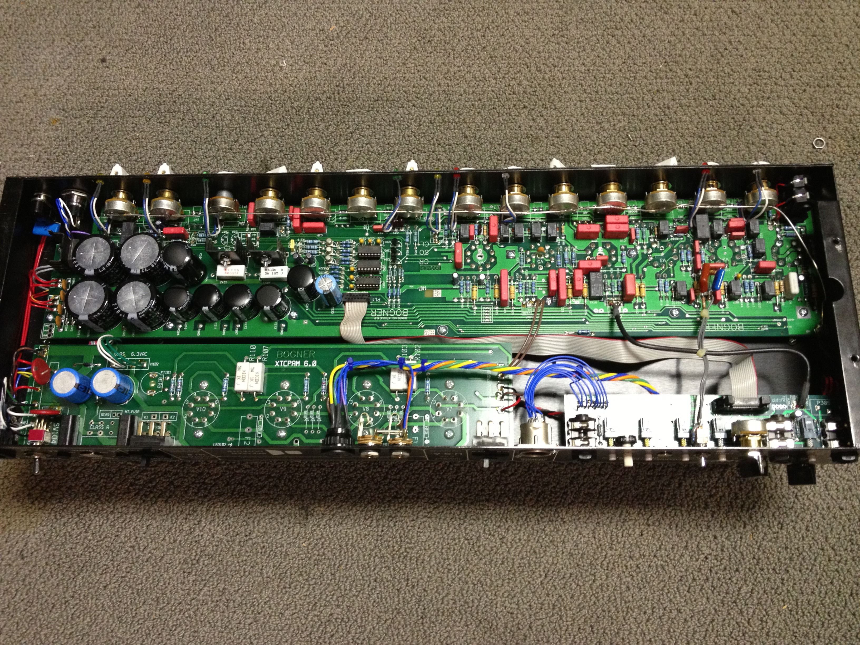
Notice sockets straight to PCB, pots too, filaments fed using PCB tracks, ultra compact "4 gallon contents inside a 2 quart bottle" ..... quite contrary to what´s "intuitive", and yet .... they work and are made by the hundreds or thousands.
They seem to defy all rules ... or at least quite a few, yet ......
Talking mainstream factory ones, not "Boutique" ones which are handmade, keep 50´s technology and sound, etc.
Some PCBs are *scary* even to look at, go figure.
Notice sockets straight to PCB, pots too, filaments fed using PCB tracks, ultra compact "4 gallon contents inside a 2 quart bottle" ..... quite contrary to what´s "intuitive", and yet .... they work and are made by the hundreds or thousands.
They seem to defy all rules ... or at least quite a few, yet ......
They also are a service nightmare. Things go noisy and now you have hundreds of solder joints to check. I don't think most of these PCB-based guitar amps will still be in service 50 years from now like blackface Fenders are.
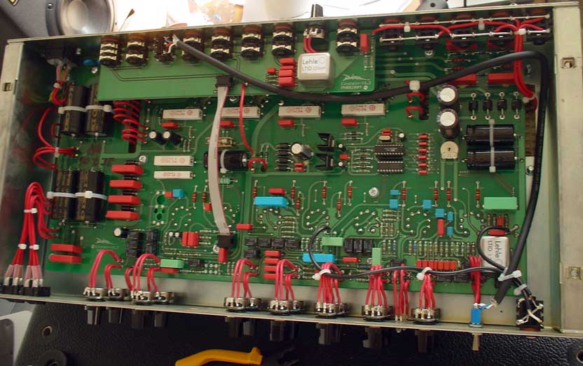
The first one seems the Bogner XTC and the second a Diezel Heinstein (I guess from the layout of the pots), those amp will be still serviced in 50 years just because they cost some thousand euros even when used, and because are considered a status symbol in the guitarist niche.
Other cheaper amps (think about the Laney VH100R) that mix smd and hole through, crowding the chassis with pcbs, will be trashed or gutted and rebuilt with something else.
The reason of this increased number of components and therefore pcbs in a is that most guitar players (that are not yet taken the emulators way) want to have the versatility of the rack era in terms of variety of sounds and interactions with other equipments (MIDI PC and CC compatibility, USB preset loading), but with the "head and cabinet" aesthetical approach. Plus, the dimensions of the head are limited by standard 2x12" and 4x12" top dimensions, that are quite standardized.
Last years have seen a decrease of power and dimensions, as you are underlying, with 30W small multi-channel midi-compatible heads (and included power reducers) specifically designed as personal monitor onstage: even less space for the same specs.
Thanks for the feedback, I think I will stick to the traditional build and allows easy mods and repairs
There are many PCB amps for which you can find schematics, and there are point-to-point hand-wired amps that don't publish schematics (e.g. older Mesa's). There is no coupling between the two.
Many PCB amps got a bad rap for serviceability when costs were cut using single layer boards with components on top and pads on bottom. There's no reliable way to desolder components without removing the boards, unlike previous eyelet and turret construction. A modern board with dual-sided plated holes remedies many of these complaints, as you can heat the joint and remove the solder easily from the top, making it only slightly harder than removing from an eyelet (for example).
PCB's are great for making hundreds of amps because it makes as much as possible repeatable: no more chopstick poking to perfect lead dress, etc. Probably not so much of a consideration for one-offs done by hobbyists, however quick-turn PCB's have reduced in cost so much it's almost easier to do one-off PCB's than to handwire prototypes. In fact, I almost never handwire a prototype of anything these days when I can get a professional PCB from CAD to my door in often a matter of a week (typically less than $10), often arriving faster than the components do.
My point was that now there are lot of small-run bespoke boards, which do not have published schemas. A point to point layout is visible, even if it is hard work to decipher. Multi layer boards, tucked away, and not so easy to unravel if they need to be maintained.
Maybe this has been commented on before - but when I build there are some parts that are best point to point wired (heaters maybe, or where you have higher watt resistors etc) and in other cases its much easier and reliable to use a PCB (maybe a CCS for example).So using modular PCBs can make life very easy when building, and I see a good few commercial amps using that type of approach. It can also make a build more reliable and neater in the end, but will not be the most compact way to build.
I install stoppers on the tube socket and run wires to the board... What way the board can go anywhere there's room.
Superposition says that Z1+Z2 = Z2+Z1, so it really shouldn't matter in which end of the wire the grid stopper is. You can put it on the board.
Or as my honours advisor in college said: "The inductor doesn't know which end of the wire it's in".
Tom

Be careful with the traces for GND, parasitic capacitance.
Grid stoppers should be very very close to socket, even the cathode resistor should be very close to socket.
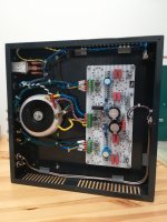
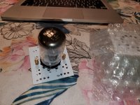
One of my pcb design and final amplifier build in photo bellow 🙂
 someone putting the components on the non hot side.. finally! The number of 'high end' I see that simply shove the caps and resistors against the tubes radiating lovely heat and immediately I see the meme "I R Dissapoint".
Still.. if they get low THD figures they can wave..
My general rule is, I never solder tube sockets directly to PCBs, even though it would be convenient and cost efficient.
I do not like heating/cooling cycles that cause mechanical stress. Also, such a way I can route components to minimize coupling between them and traces, and through the traces, instead of routing around the tube pin-out.
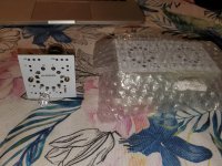
Something like this? I could see how this construction method would conduct far less heat down the tube pins, into the traces and needlessly heat up the other parts. Also it offers flexibility in alternative wiring for different bases and pin outs, positioning the grid stoppers, in future servicing of the amp, etc.

Something like this? I could see how this construction method would conduct far less heat down the tube pins, into the traces and needlessly heat up the other parts. Also it offers flexibility in alternative wiring for different bases and pin outs, positioning the grid stoppers, in future servicing of the amp, etc.
View attachment 978133
Looks good to me. The boards are narrow, good for convection. I prefer to mount boards vertically, so resistors are open to convection too. But since I bought helluva Compactron PCB mount vintage sockets, I made small boards for them, with proper connections and few components that is better to keep closer to tubes.
Attachments
Folks, is there any recommendation for the inter-tube spacing of 12AX7 type tubes on a pcb?
For power tubes, I follow the one and half times tube diameter rule. That seems excessive for small tubes.
For power tubes, I follow the one and half times tube diameter rule. That seems excessive for small tubes.
Folks, is there any recommendation for the inter-tube spacing of 12AX7 type tubes on a pcb?
I think it best to leave at least the width of a single tube in between each tube. To be safe. If it's a 12AX7 with less than 1mA of plate current, maybe they could be placed a bit closer together. But then will there be any coupling effects between the tubes? That I don't know.
Does it make sense to make PCBs to hold the passive parts and other support circuitry (e.g., plate CCS, coupling RC, cathode RC or LED, , while chassis mounting the tube sockets off the PCBs? I'm assuming the tube sockets would be located as close as possible to the PCBs holding each tube's supporting circuitry. Maybe leave a cutout in the PCB for each tube socket, expanding on what the photos show in post #75?
I don't like the idea of putting traces on the PCB for the heater supply. I leave pads on the PCB for running twisted pair wiring from the heater transformer secondary or a regulated DC heater supply straight to the heater pins on the tube(s). You're just using a bit longer run of hookup wire, and it helps keep heater currents from coupling into audio signal traces.
I have designed numerous valve amps using PCB and not had any problems.Hi All, I have always though using PCBs with valves adds complications due to the high voltages compared to the traditional pin point wiring.
Have any of you witnessed any problems with the PCB method?
A little care is needed with HV, input circuit and hum.
- Home
- Amplifiers
- Tubes / Valves
- General rules for designing PCB for valve amplifiers