Ground planes do makes sense in audio, but not so much in tube circuits due to the high voltage.
Auto-routing makes no sense anywhere, especially in audio. At least I've yet to see one create a good layout.
Don't go crazy with star grounding. Recall that the point of star grounding (and ground planes) is to keep large currents away from quiet circuits. So you can have the "quiet grounds" come together and the power grounds come together and join the two at one spot. Routing each component that's connected to ground via its own trace to a ground star gets really unwieldy.
Note that the power supply lines often have the same problem as grounds. Make sure to feed sensitive circuits from a supply line that is not bouncing around due to the current draw of a heavy load (like the output tubes).
Oversize the pads for hand soldering. You'll thank yourself if you ever need to de-solder anything.
Make the traces wider than minimum width. 15-20 mil (0.4-0.5 mm) is usually good for low currents. You definitely want to go beefier on higher currents (like the heater traces).
Watch the trace spacing - including on connectors. Note that connectors and resistors have maximum voltage specs. Stay below them.
I would probably route the heater traces first. Then the signal path. Then everything else.
Spend lots of time on the component placement. Layout is easy (or easier) if the components are placed well.
The Saturn PCB Toolkit is a good resource for trace width, spacing, etc.: Saturn PCB Toolkit - Saturn PCB Design | Saturn PCB Design
Regular 1.6 mm FR-4 with 1 oz (35 um) copper is plenty. If you're concerned about the board flexing from inserting tubes into sockets, place mounting holes on either side of the tube socket or have a large cutout in the board and wire through it to a chassis-mounted tube socket.
Tom
Don't go crazy with star grounding. Recall that the point of star grounding (and ground planes) is to keep large currents away from quiet circuits. So you can have the "quiet grounds" come together and the power grounds come together and join the two at one spot. Routing each component that's connected to ground via its own trace to a ground star gets really unwieldy.
Note that the power supply lines often have the same problem as grounds. Make sure to feed sensitive circuits from a supply line that is not bouncing around due to the current draw of a heavy load (like the output tubes).
In SMPS they keep high dI/dt loops as small as possible. That's the loop between the caps, inductor and the switching. I assume the same in terms of layout for signal especially the power side of things.
Also feedback is kept far away from that high noise area - same technique for feedback of audio.
I remember a YouTube video of a 'high quality tube amp' recently using a volume pot with two tubes orientated so the plates were facing it full on, next to the tubes the caps were positioned.. just right to get nice and toasted.
It would have been better to have the cap and the volume away from the tube - even simply putting them on the underside would have been good where the cool air can be drawn from underneath.
I think of tube placement in a similar way - thinking of quiet sides/areas vs noisy side/areas. Also for cool side vs hot side.
^^^^^^ That.So you can have the "quiet grounds" come together and the power grounds come together and join the two at one spot. Routing each component that's connected to ground via its own trace to a ground star gets really unwieldy.
In my Power amps (SS , meant for Musical instruments) I typically draw 2 grounds, a "clean" one for Signal purposes, and a "don´t care" one meant for high currents and speaker return.
IF needed, speaker return gets its own dedicated one, and in ALL cases transformer center tap gets soldered straight to the large copper slab joining Power capacitors in series.
Just halfway between them, which are almost touching body to body.
I do NOT want capacitor charging currents (which are HUGE and have funky peaky harmonic rich waveforms) injected anywhere else, period.
Holes for sockets
Regarding not having the tube socket attached to the PCB, I was thinking of something along the lines of Quad II driver boards. I plan to try 6BR7 instead of EF86 at some point, and the different pinout will not be an issue....
Old Hector, ... Sketch something up, I might take a look if I get the bug.
Attachments
Friend, one suggestion: nice design but I strongly suggest you increase socket pin pad sizes; since they have a larger than usual hole, you only left the tiniest copper ring around.Never mind...
Doubly problematic because tubes are heavy and users push /pull tubes in/out by hand, a strong and very uneven pressure.
Even worse: users often wiggle tubes for easier insertion or removal.
If you do a layout with chassis-mounted tube sockets and the passive parts on a PCB, what would be the best way to wire up grid stoppers and build out resistors? 'Flying' from the PCB to the pin on the tube sockets? That would limit the distance between the socket and the PCB.
Friend, one suggestion: nice design but I strongly suggest you increase socket pin pad sizes; since they have a larger than usual hole, you only left the tiniest copper ring around.
Doubly problematic because tubes are heavy and users push /pull tubes in/out by hand, a strong and very uneven pressure.
Even worse: users often wiggle tubes for easier insertion or removal.
What are the ramifications of larger pin socket pads being extremely close to each other? Wouldn't that increase stray capacitance between pins (pads)?
If you do a layout with chassis-mounted tube sockets and the passive parts on a PCB, what would be the best way to wire up grid stoppers and build out resistors? 'Flying' from the PCB to the pin on the tube sockets? That would limit the distance between the socket and the PCB.
I install stoppers on the tube socket and run wires to the board... What way the board can go anywhere there's room.
Attachments
When you have 2 thin copper disks side by side but still at *some* distance, mutual capacitance is very low.
I find the distinct possibility of tearing way too thin copper rings and/or developing hairline cracks between pad and track a more worrying concern.
I also suggest adding fillets at track to pad joints.
As in:
PCB 101: Include Teardrops in Your Designs to Save You Tears Later
I find the distinct possibility of tearing way too thin copper rings and/or developing hairline cracks between pad and track a more worrying concern.
I also suggest adding fillets at track to pad joints.
As in:
PCB 101: Include Teardrops in Your Designs to Save You Tears Later
I install stoppers on the tube socket and run wires to the board... What way the board can go anywhere there's room.
I've done that in point-to-point wired builds. The flying resistors make me nervous, so I've taken to heatshrinking those. So far that's worked fine. No short-outs, broken off resistors, etc.
I suppose one could take a PCB with pads for onboard tube sockets and wire it up with chassis-mount sockets. Jumper the pads for grid stopper Rs, etc. on the PCB, wire them up to the socket pins, like you've done.
Do you think that could cause problems in a low signal/high gain circuit like a phono preamp?

Not sure if it's been discussed- but I think tube socket pin holes in PCB's should all be vias... Pads both side of PCB and metal thru the hole.
I used the Newark trace width calc also- finding there's important tradeoff of amperage/width V thermal gradient.
Something I considered was to unmask filament traces & fill w/ solder during assembly to augment current capability.
Jim
I used the Newark trace width calc also- finding there's important tradeoff of amperage/width V thermal gradient.
Something I considered was to unmask filament traces & fill w/ solder during assembly to augment current capability.
Jim
Attachments
I find the ability of pcb layout to "Highligh Net Connection" very useful, it will sound an alarm when the net is missing (as reference netlist to schematic ) a component or more or incomplete. This will give much assurance as you layout is correct before you send for fabrication. It useful even for manual wiring at the back side of pcb, with image flipped so make it easy to wire up.
Do you know any other software has this feature?
Do you know any other software has this feature?
Attachments

The other thing is how to solder the 9/8 pin socket so that it does not shake or move. You can bolt down the socket to pcb through the socket hole in the middle and hole in pcb, then solder all the pins to pcb. You can the try to plug it a tube to see it fits, insert an old tube to test or use rivet pin of a little smaller diameter than the tube pins
Wiring an amplifier is like a PCB without FR4.
So why not PCB for valve amplifiers?
Three thing to consider when using PCB:
- as pointed by @Wavebourn, thermal management; applies for tube sockets and also for heat generating components like plate or cathode power resistors (if possible out of the case then generally they´re some electrolytics used); I´m using HQ noval, octal or UX4 sockets from CMC (PCB definition for noval allows only creepage up to 200V); I´m also using Beltron ones or custom ones (loctal); I´m mounting Jumbo sockets using metal spacer
- heater supplies routing on PCB is tricky: personally I prefer twisted cable and connector (MicroMatch are nice for low current applications); twisted routing is also possible using alternate layer swapping
- respect creepage and clearance; use slots, or put HV in inner layer (if you´re using multilayer PCB) to increase creepage; don´t forget to calculate this values at no load
I´m always trying to replace electrolytic with film capacitors (KEMET, WIMA, PANASONIC).
I´m using KEYSTONE 500x testpoints.
I´m mounting sockets and heating components (if possible) on top side and all the rest on bottom side.
I´m mounting the PCB on a custom aluminium plate (Schaeffer Apparentbau), so testing and measurements only on bottom side and very easing.
My two cents.
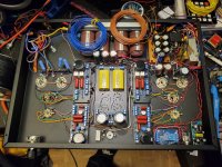
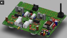
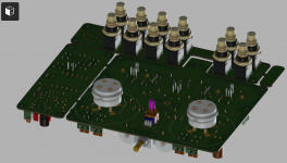
PS: find 3D view of Ale (Bartola) 300B preamplifier (if I remain correctly, only 250VDC max.) attached.
JP
So why not PCB for valve amplifiers?
Three thing to consider when using PCB:
- as pointed by @Wavebourn, thermal management; applies for tube sockets and also for heat generating components like plate or cathode power resistors (if possible out of the case then generally they´re some electrolytics used); I´m using HQ noval, octal or UX4 sockets from CMC (PCB definition for noval allows only creepage up to 200V); I´m also using Beltron ones or custom ones (loctal); I´m mounting Jumbo sockets using metal spacer
- heater supplies routing on PCB is tricky: personally I prefer twisted cable and connector (MicroMatch are nice for low current applications); twisted routing is also possible using alternate layer swapping
- respect creepage and clearance; use slots, or put HV in inner layer (if you´re using multilayer PCB) to increase creepage; don´t forget to calculate this values at no load
I´m always trying to replace electrolytic with film capacitors (KEMET, WIMA, PANASONIC).
I´m using KEYSTONE 500x testpoints.
I´m mounting sockets and heating components (if possible) on top side and all the rest on bottom side.
I´m mounting the PCB on a custom aluminium plate (Schaeffer Apparentbau), so testing and measurements only on bottom side and very easing.
My two cents.
PS: find 3D view of Ale (Bartola) 300B preamplifier (if I remain correctly, only 250VDC max.) attached.
JP
Attachments
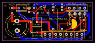
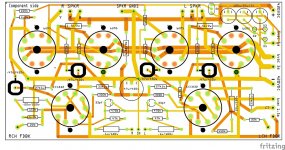
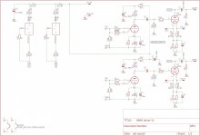
My E86C 6B4G driver PCB- Make a PCB phototread?
As long as we are posting examples. Perhaps make a sticky for diy PCB artwork?
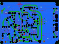
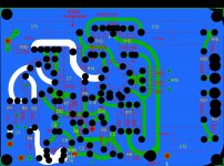
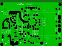
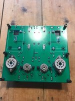
Heres a board i did for a forum member, E86C RC stage, feeding into a CCS loaded 6B4G for driving a GM70.
Mind you i used grid stoppers on every grid connection of the E86C to curb oscillation.
Belton sockets for everything, i forgot to put drill holes in the center of the 6B4G, stupid mistake.
All resistors are mounted slightly off board by means of ceramic tubes that slide over the leads.
Note that i use plastic standoffs near the tube sockets nowadays, this is experimental, i dont know if they stand up to the heat.
As long as we are posting examples. Perhaps make a sticky for diy PCB artwork?
Heres a board i did for a forum member, E86C RC stage, feeding into a CCS loaded 6B4G for driving a GM70.
Mind you i used grid stoppers on every grid connection of the E86C to curb oscillation.
Belton sockets for everything, i forgot to put drill holes in the center of the 6B4G, stupid mistake.
All resistors are mounted slightly off board by means of ceramic tubes that slide over the leads.
Note that i use plastic standoffs near the tube sockets nowadays, this is experimental, i dont know if they stand up to the heat.
Attachments

Thanks folks!
Denny, really interested to know more about when you use ground planes successfully. From what I understand there is a trade off between ground plane and star-ground. If significant current is flowing in the ground plane then there will be voltage drops and noise currents; star-ground minimises this but is more susceptible to magnetic induction. See answer here:
operational amplifier - Single point vs Ground plane, in audio OP AMP PCB layouts - Electrical Engineering Stack Exchange
Anyway, I don't want to get off topic! This is about gathering best practices, so thanks, I'm just trying to understand better.
It must be obvious to someone with more experience, but what do you mean that you only recommend ground planes with boards with solder masks?
Nick, Nigel, would be interested in some photos of those PCB with short leads. I don't like the idea of tube sockets on PCBs either, but I'm trying to be pragmatic. I must prefer to chassis moubt an hook up later. But decided keeping things simple is the best approach right now.
Old Hector, maybe we should just put a small robot arm inside the chaisse so it can rewire everything while I'm making a cup of tea 😉 joking aside, yes would be cool. Sketch something up, I might take a look if I get the bug.
Ground planes are fine if you isolate them from each other and they connect only at one point, for example in my full function preamp, the phono stage has it's own ground plane, the same with the line stage, and heater supply has it's own ground plane, and all three connect at a single point, which then connects to the main power supply on a seperate board.
- Home
- Amplifiers
- Tubes / Valves
- General rules for designing PCB for valve amplifiers