But it is well known that Webster's equation is wrong,
The error is not with the equation, but in its application.
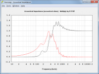
Used appropriately, Webster can give a reasonably accurate prediction of the throat acoustical impedance of an OSWG, required if acoustical power is to be determined.
The light traces show an infinite horn, the dark traces show the finite horn.
Attachments
This appears to be a view that is somewhat at odds with accepted practice. Are you able to provide links to work that supports it or perhaps expand a bit more? Thanks.I have never made a device with a rectangular cross section. It just doesn't make any sense to me to do that since the source is not rectangular. I have made elliptical section devices and they work just as expected, but are significantly harder to work with and in the end I found little to no advantage in doing so. I just stick with round. They may look boring, but I have not found anything that works better.
If all you care about is the acoustical impedance of the lowest mode at the throat then Webster works OK (it is still a rough approximation, not exact as the OS is when done properly. And the two don't give the same answers - the exact OS is clearly the correct one.) I find the information provided from Webster of little practical use and no use at all in finding the devices directivity.The error is not with the equation, but in its application.
Used appropriately, Webster can give a reasonably accurate prediction of the throat acoustical impedance of an OSWG, required if acoustical power is to be determined.
I did not publish any of my work in this area, but the result is simple to see. An elliptical device has a narrower vertical directivity at HFs, but it also has a narrower vertical dimension so it does not control the polar to as low a frequency as the horizontal. This is a problem, a bigger problem IMO than the round device having a wider directivity vertically but better control. Remember that when the device looses control the pattern widens, not narrows, so that at the lower end the elliptical and the round both have about the same directivity, but the elliptical is changing more than the round. This will negate the main benefit claimed for the narrower vertical coverage as regards the crossover lobbing. If you want to make the elliptical as high as the round then with its wider mouth it grows to an extreme size becoming impractical.This appears to be a view that is somewhat at odds with accepted practice. Are you able to provide links to work that supports it or perhaps expand a bit more? Thanks.
In theory, there is nothing wrong with a narrower vertical coverage, it is just that in practice it never works out that well. This is based on real data, not theory. In my products the cost of going elliptical would be nearly double that of a round device (manufacturing realities.) For no real benefit except marketing I did not find this an attractive tradeoff.
No one has bothered to work it out, basically because it doesn't have a wide interest level I suppose.So what is the equation pos was after? 🙂
Thanks for the expansion. Here is an example (click Measurements on the RHS) that I believe supports to a fair extent what you say. The elliptical waveguide for the tweeter looks fine but the vertical control for the midrange looks to have been lost. Perhaps it is the best compromise but it doesn't look neat and tidy.I did not publish any of my work in this area, but the result is simple to see. An elliptical device has a narrower vertical directivity at HFs, but it also has a narrower vertical dimension so it does not control the polar to as low a frequency as the horizontal. This is a problem, a bigger problem IMO than the round device having a wider directivity vertically but better control. Remember that when the device looses control the pattern widens, not narrows, so that at the lower end the elliptical and the round both have about the same directivity, but the elliptical is changing more than the round. This will negate the main benefit claimed for the narrower vertical coverage as regards the crossover lobbing. If you want to make the elliptical as high as the round then with its wider mouth it grows to an extreme size becoming impractical.
The 600Hz and 2kHz defects in vertical directivity correspond to the crossover frequencies.
David
David
Is the Glass Only Half Full or Just Half Empty
Hi Earl,
Some comments follow.
Did you get the paper?
Regards,
Bill
For frequency spectrum top down design, true. But at the low end, were pattern control is a non-issue, Webster works just fine as a design tool for those that want to park an '18-wheeler' in their driveway at home.
If you start with a round section horn of a certain size and mission, and then increase its mouth size in the horizontal plane only, you have not reduced pattern control in the vertical dimension by doing so, but you have certainly widened the dispersion pattern in the horizontal plane. In his setting it is incidental that control in horizontal plain has also been extended to a lower frequency, well below the c/o frequency intended to be used with both designs. With this exception, I otherwise agree entirely with the content of this post.
Do not give the 'fish', just give, 'the how to fish'.
I used to post formula here, but I am still waiting for some mathematical feedback on those earlier submissions.
Hi Earl,
Some comments follow.
Did you get the paper?
Regards,
Bill
If all you care about is the acoustical impedance of the lowest mode at the throat then Webster works OK (it is still a rough approximation, not exact as the OS is when done properly. And the two don't give the same answers - the exact OS is clearly the correct one.) I find the information provided from Webster of little practical use and no use at all in finding the devices directivity.
For frequency spectrum top down design, true. But at the low end, were pattern control is a non-issue, Webster works just fine as a design tool for those that want to park an '18-wheeler' in their driveway at home.
I did not publish any of my work in this area, but the result is simple to see. An elliptical device has a narrower vertical directivity at HFs, but it also has a narrower vertical dimension so it does not control the polar to as low a frequency as the horizontal. This is a problem, a bigger problem IMO than the round device having a wider directivity vertically but better control. Remember that when the device looses control the pattern widens, not narrows, so that at the lower end the elliptical and the round both have about the same directivity, but the elliptical is changing more than the round. This will negate the main benefit claimed for the narrower vertical coverage as regards the crossover lobbing. If you want to make the elliptical as high as the round then with its wider mouth it grows to an extreme size becoming impractical.
In theory, there is nothing wrong with a narrower vertical coverage, it is just that in practice it never works out that well. This is based on real data, not theory. In my products the cost of going elliptical would be nearly double that of a round device (manufacturing realities.) For no real benefit except marketing I did not find this an attractive tradeoff.
If you start with a round section horn of a certain size and mission, and then increase its mouth size in the horizontal plane only, you have not reduced pattern control in the vertical dimension by doing so, but you have certainly widened the dispersion pattern in the horizontal plane. In his setting it is incidental that control in horizontal plain has also been extended to a lower frequency, well below the c/o frequency intended to be used with both designs. With this exception, I otherwise agree entirely with the content of this post.
No one has bothered to work it out, basically because it doesn't have a wide interest level I suppose.
Do not give the 'fish', just give, 'the how to fish'.
I used to post formula here, but I am still waiting for some mathematical feedback on those earlier submissions.
Last edited:
Indeed but my point concerned the beam width for the midrange in the vertical plot. If you eyeball the geometry it should be something like 60 degrees but the measurements show the waveguide has lost control and it is more like 120 degrees. The horizontal on the other hand roughly agrees with the geometry at 90 degrees. For the tweeter both the vertical and horizontal measured beam widths roughly agree with the geometry.The 600Hz and 2kHz defects in vertical directivity correspond to the crossover frequencies.
I am not trying to "branch out on my own" or disregarding previous art.My suggestion would be that you try and understand why the people who have done this stuff their whole lives do things the way that they do. Trying to "branch out on your own" is not likely to be very effective till you understand why things are the way they are now.
I want to experiment, and I am by no mean pretending to revolution anything, or even create something new.
Actually there is nothing new here.
Here is how Newell describes a radial horn (from Loudspeakers for music recording and reproduction)
The walls controlling the horizontal directivity are set to the desired coverage angle. The shape of the other two walls is adjusted to maintain an overall exponential flare, resulting in a less-than-ideal vertical directivity
Yuchi Arai method in calculating his horns is exactly that: Woodcraft horn
Finally, the TAD TH4003 horn is even closer to what I want to do here: the horizontal profile is almost straight (with rounding at the throat and mouth) and without fins, and the vertical profile is adjusted for an hypex expension with the hypothesis of a purely spherical wavefront in the horizontal plan (starting at the phasing plug).
The vertical profile even narrows a few centimeters after the throat to compensate for the rapid extension in the horizontal plan.
I would like to use an OS profile for the horizontal plan because it makes it easy to match a given exit angle and then transition to a straight profile in the best possible way.
If everyone had to fish to survive then they would obviously have less time to work on others things and we would still live in caves...Do not give the 'fish', just give, 'the how to fish'.
Fundamentally, to continue a little longer with the same metaphor, I don't want to learn how to fish: I do not have the time and knowledge to fully master the mathematics involved here.
That is why I am asking for a little help here from people that do have this knowledge.
I also have done my share of sharing on these forums.
Give me that damn fish! 😀
(and if it taste good I might even learn how to fish one day, I promess)
Horn Shape Optimization
The technology has advanced well beyond this. See the body of work referenced in the attached paper [1] The wide spectrum shapes produced, bear a marked resemblance to the shape of a L'Cleac'h horn. I suspect that the ideal bounding condition can be achieved by adjusting the parameters of a Euler's (Cornu's) Spiral Segment [2]. For horns with sectional aspect ratios > 1, the modeling challenge is increased by at least a magnitude in difficulty.
Regards,
WHG
[1]
Title: Fixed-mesh curvature-parameterized shape optimization of an
acoustic horn
Authors: Fotios Kasolis, EddieWadbro & Martin Berggren
[2] Clothoid Curve
Cornu Spiral -- from Wolfram MathWorld
When you have a horn that is not axisymmetric, thing are a bit tricky because the wave front is going to vary. Probably some 3D BEM simulations can give a general idea what is involved.
The technology has advanced well beyond this. See the body of work referenced in the attached paper [1] The wide spectrum shapes produced, bear a marked resemblance to the shape of a L'Cleac'h horn. I suspect that the ideal bounding condition can be achieved by adjusting the parameters of a Euler's (Cornu's) Spiral Segment [2]. For horns with sectional aspect ratios > 1, the modeling challenge is increased by at least a magnitude in difficulty.
Regards,
WHG
[1]
Title: Fixed-mesh curvature-parameterized shape optimization of an
acoustic horn
Authors: Fotios Kasolis, EddieWadbro & Martin Berggren
[2] Clothoid Curve
Cornu Spiral -- from Wolfram MathWorld
Attachments
Thanks for the expansion. Here is an example (click Measurements on the RHS) that I believe supports to a fair extent what you say. The elliptical waveguide for the tweeter looks fine but the vertical control for the midrange looks to have been lost. Perhaps it is the best compromise but it doesn't look neat and tidy.
Clearly making the waveguides elliptical did not alleviate all the problems. Whether it is better or worse is unknown. In what I was doing I did not see enough improvement to warrant the costs.
Those waveguides won't have much control (too small) so the differences would tend to be negligible. It's when you have a large waveguide like my 18" device that the tradeoffs are not a good option IMO.
Bill
Yes, staring with the height of the waveguide that gives you control down below the crossover frequency and then widening it to get the wider horizontal pattern does work, but it yields one very big device if one is looking for 700-800 Hz crossover to the waveguide. As I have said it is all about the tradeoffs, not that a narrower vertical directivity is undesirable - just not a good tradeoff.
And no I did not see the paper. I believe that I have read [1]. If its the one that I am thinking about it is really quite good. I was impressed that after all their analysis they ended up with something very close to the OS, which is almost 25 years since I wrote about it and more than 60 years since Freehafer. The obsession with "loading" blindsided people IMO. (Even Freehafer did not understand the significance of knowing the wave front shape. He only ever talked about loading.) When you don't care about loading, but only directivity, then you quickly realize that Webster is a waste of time.
Last edited:
Hi Bill, Earl
The problem with asymmetric patterns is that if one makes the simple way and has more than about 1.5:1 pattern aspect, it will produce enough pattern flip to be a problem.
The more asymmetric the simple horn is, the more pronounced the pattern flip is.
A classic example, the EV t-350/35 has similar shape of Patrick’s horn earlier which he noticed didn’t sound that good. The 350 had pattern flip that began around 10K and below and so to get wide horizontal dispersion, the recommended mounting was up and down not side to side. An oval mouth and it’s corresponding internal angles would be similar.
Our biggest horns at work don’t have pattern flip but they do have the mouth geometry that is needed as inferred through Keele’s pattern loss thumb rule. To lose pattern control in both planes at the same frequency (and avoid the problem) , if the horizontal pattern is twice the vertical angle, then the height has to be twice the width. This is the opposite profile of the simple horn and one has entered the realm of the astigmatic point source haha.
Best,
Tom Danley
Addendum -
No that is not the paper that I thought. It is kind of pointless - flare the mouth for lower internal reflections! DA!
There was a superb thesis in Australia some years back about shape optimization for the best far field polar response. That paper was a very good piece of work.
No that is not the paper that I thought. It is kind of pointless - flare the mouth for lower internal reflections! DA!
There was a superb thesis in Australia some years back about shape optimization for the best far field polar response. That paper was a very good piece of work.
Hi Bill, Earl
The problem with asymmetric patterns is that if one makes the simple way and has more than about 1.5:1 pattern aspect, it will produce enough pattern flip to be a problem.
Best,
Tom Danley
Hi Tom - that's basically what I was saying, but with a different terminology. I tend to steer clear of terms like "Pattern-flip" that aren't widely know around here.
You Dog is Not Hunting Well Here!
The name of this forum starts with the initials DIY. If you do not want to go fishing for your fish, then go to the market and buy your fish. I have already given you a design regime to follow. Now you want me to produce a solution here in all its mathematical rigor for free. Well yes, that is not happening here, because my time, to me, is just as valuable as yours is to you. When asking for help for free, you are not in a position to dictate the terms, conditions and the extent of the help you receive. If you are not prepared to get your mind around the simple math required here, then even if I produce the formula for you, you would still remain clueless as how to use them.
WHG
If everyone had to fish to survive then they would obviously have less time to work on others things and we would still live in caves...
Fundamentally, to continue a little longer with the same metaphor, I don't want to learn how to fish: I do not have the time and knowledge to fully master the mathematics involved here.
That is why I am asking for a little help here from people that do have this knowledge.
I also have done my share of sharing on these forums.
Give me that damn fish! 😀
(and if it taste good I might even learn how to fish one day, I promess)
The name of this forum starts with the initials DIY. If you do not want to go fishing for your fish, then go to the market and buy your fish. I have already given you a design regime to follow. Now you want me to produce a solution here in all its mathematical rigor for free. Well yes, that is not happening here, because my time, to me, is just as valuable as yours is to you. When asking for help for free, you are not in a position to dictate the terms, conditions and the extent of the help you receive. If you are not prepared to get your mind around the simple math required here, then even if I produce the formula for you, you would still remain clueless as how to use them.
WHG
Good to Hear form You
Hi Tom,
Thanks for the KISS.
You are correct, avoid the extremes, but tweaking in the margins is still possible. I will revisit Keel's paper to see if I have gone astray somehow.
Regards,
Bill
Hi Bill, Earl
The problem with asymmetric patterns is that if one makes the simple way and has more than about 1.5:1 pattern aspect, it will produce enough pattern flip to be a problem.
The more asymmetric the simple horn is, the more pronounced the pattern flip is.
A classic example, the EV t-350/35 has similar shape of Patrick’s horn earlier which he noticed didn’t sound that good. The 350 had pattern flip that began around 10K and below and so to get wide horizontal dispersion, the recommended mounting was up and down not side to side. An oval mouth and it’s corresponding internal angles would be similar.
Our biggest horns at work don’t have pattern flip but they do have the mouth geometry that is needed as inferred through Keele’s pattern loss thumb rule. To lose pattern control in both planes at the same frequency (and avoid the problem) , if the horizontal pattern is twice the vertical angle, then the height has to be twice the width. This is the opposite profile of the simple horn and one has entered the realm of the astigmatic point source haha.
Best,
Tom Danley
Hi Tom,
Thanks for the KISS.
You are correct, avoid the extremes, but tweaking in the margins is still possible. I will revisit Keel's paper to see if I have gone astray somehow.
Regards,
Bill
Well, that last statement in bold in my post was of course a bit of a joke: I am certainly not asking anyone to spend their time doing things they don't want to, and I thank you for the information you were willing to give me.The name of this forum starts with the initials DIY. If you do not want to go fishing for your fish, then go to the market and buy your fish. I have already given you a design regime to follow. Now you want me to produce a solution here in all its mathematical rigor for free. Well yes, that is not happening here, because my time, to me, is just as valuable as yours is to you. When asking for help for free, you are not in a position to dictate the terms, conditions and the extent of the help you receive. If you are not prepared to get your mind around the simple math required here, then even if I produce the formula for you, you would still remain clueless as how to use them.
WHG
I came here to ask a simple question: if somebody had that OS expansion formula at hand, or could deduce it easily. In response I got lessons and demeaning remarks.
I don't think the definition of a DIY community should read "everyone should do everything on its own", but rather something like "everybody should do his share", and as already said I think I have done my share for this community (and spent a lot of time doing so for free, mind you).The name of this forum starts with the initials DIY
Last edited:
HSO Notes
If you look at the body of this work, not just the one paper provided here, you will find that both issues are addressed by the optimization problem.
As Freehafer points out the only difference between a conical and OS (his hyperbolic) horn is in the neck geometry. So that is where the dispersion pattern differences must be coming form. As the underlying assumption is of a horn of infinite extent, the theory falls apart somewhat when these horns are now made finite and the discontinuity of a mouth takes effect. So why not use this technology to minimize the attendant reflectance and back-wave propagation. Of course you can just throw an arbitrary radius and call it a day.
I will look for this paper if I do not already have it.
As I recall it also deployed Shape Optimization Technology as well.
Regards,
Bill
Addendum -
No that is not the paper that I thought. It is kind of pointless - flare the mouth for lower internal reflections! DA!
If you look at the body of this work, not just the one paper provided here, you will find that both issues are addressed by the optimization problem.
As Freehafer points out the only difference between a conical and OS (his hyperbolic) horn is in the neck geometry. So that is where the dispersion pattern differences must be coming form. As the underlying assumption is of a horn of infinite extent, the theory falls apart somewhat when these horns are now made finite and the discontinuity of a mouth takes effect. So why not use this technology to minimize the attendant reflectance and back-wave propagation. Of course you can just throw an arbitrary radius and call it a day.
There was a superb thesis in Australia some years back about shape optimization for the best far field polar response. That paper was a very good piece of work.
I will look for this paper if I do not already have it.
As I recall it also deployed Shape Optimization Technology as well.
Regards,
Bill
'The vertical profile even narrows a few centimeters after the throat to compensate for the rapid extension in the horizontal plan"
POS,
This is a classic mathematical error in traditional radial horns. It is caused by the transition from the throat section to the flare section and was a common problem joining the two sections. This is driven by trying to follow the classic exponential expansion rate and you will see this in all the earlier Altec and JBL horns. This is one area that the old methods of looking only at expansion rate fail and don't account for directivity. There are better ways to do this and this is where you should look if you want to improve on a radial type horn.
- Home
- Loudspeakers
- Multi-Way
- Geddes on Waveguides