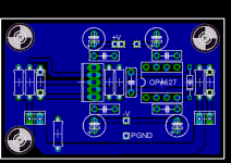
Things have not changed much atm, just the replacement of the Stand off holes, and the repositioning of the +V decoupling cap.
I ran into a problem when i first removed the +V connector block.
As the middle pin was a ground there was a source for the ground in this area, as soon as it was removed it created an "Island", and this was the reason i turned the decoupling cap 180 degrees.
As you will see i have added to pads for a jumper to over come this island problem.
I have tried for most of the day to find a better solution, but apart from redoing the board, I can see no other viable option.
I hate using jumpers and always feel its a bit of a cop out, but I have been forced to commit the dreaded sin of putting them in there.
If someone could see a better way of rounting it to get rid of the jumpers, please feel free to guide me toward the light.
I like the idea of having the regulators onboard also, I may be working on a headphone amp once this pre is finished and would like the board to be stereo and have the supply all on one board.
If i manage this I would revisit the pre and update the design then, if someone has not done so allready.
Don't worry SvErD I have not forgot about your suggestion, and I will implement it, as I think this will give more options, for various hookup wire.
Ok, this attachment shows the loaction of the mounting holes, and the jumpers to remove the island effect.
I ran into a problem when i first removed the +V connector block.
As the middle pin was a ground there was a source for the ground in this area, as soon as it was removed it created an "Island", and this was the reason i turned the decoupling cap 180 degrees.
As you will see i have added to pads for a jumper to over come this island problem.
I have tried for most of the day to find a better solution, but apart from redoing the board, I can see no other viable option.
I hate using jumpers and always feel its a bit of a cop out, but I have been forced to commit the dreaded sin of putting them in there.
If someone could see a better way of rounting it to get rid of the jumpers, please feel free to guide me toward the light.
I like the idea of having the regulators onboard also, I may be working on a headphone amp once this pre is finished and would like the board to be stereo and have the supply all on one board.
If i manage this I would revisit the pre and update the design then, if someone has not done so allready.
In addition I'd prefer to get rid of the connectors an have bigger pads for the in/out wires.
Don't worry SvErD I have not forgot about your suggestion, and I will implement it, as I think this will give more options, for various hookup wire.
Ok, this attachment shows the loaction of the mounting holes, and the jumpers to remove the island effect.
Attachments
Hello n00ber
First of all, i see a serious fault. Before, you and I had the BW and V- pins on the BUF tied together but now when you have added option for a BW-resistor it seems that you have forgotten that the V- is actual pin 3. So if someone is using the BW resistor they will power the BW pin with the supply and the V- pin with the supply+resistor and if a jumper is used then you will have a pretty long V- trace and loosing the "100nF cap close to the pins"
Second, don't know if it's a problem but it seems that the route for the V+ to PGND has to go around the whole card and thru a 1mm wide trace close to the output resistor.
Keep it up!
Russ, are you still thinking of organizing a group buy? The board's looking pretty good (subject to that last post).Russ White said:Let not forget however that while this board is for the 627/634 it will actually support just about any single opamp (ad8610, opa227/228, opa277, LT1115, etc..) So cost is actually quite arbitrary. You could also use any buffer with the same pinout of the 634.
As it happens, I have a few BUF634s that I'd love to use...
Paul
paulb said:
Russ, are you still thinking of organizing a group buy? The board's looking pretty good (subject to that last post).
As it happens, I have a few BUF634s that I'd love to use...
Paul
Yes, I am planning on it. I think I will also do kits right off the bat with this GB. The part count is quite low. 🙂
The boards themselves will not be expensive. Very good quality PCBs(2oz copper and maybe gold plate) for the version I built can be made quite cheaply. I could probably sell them for right around $5(probably a little less) a board. All depending on quantity.
It has also been suggested to create a snap apart board with 2 channels and PS. I think this is a good idea. Depending on size those types of boards should also be quite reasonably priced.
I will start sourcing parts for a kit.
Cheers!
Another suggestion (if it is possible without much reworking) is to add another mounting hole in the bottom right corner. Having just three looks odd to me. Its all about symmetry. 😎
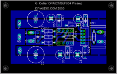
Not trying to step on any toes here, but I promised a new layout of my own about a week ago, and finally got around to finishing it. The boards are 1.75 x 2.75" ...quite small. Those big caps are intended to be 470-1000uF to hopefully clean up any ugly supply ripple and of course are optional if you are using a regulated PSU.
A few notes on this design. RF1 is the feedback resistor and is intended to mount on the bottom of the board. The pads above the resistor are inteded for a feedback cap as suggested in the BUF634 app note for use with several opamp combinations in this circut. I personally don't bother with an OPA627. RBW is the bandwidth select resistor (if some people wan't to use slower opamps you can leave this out). A resistor should cut down on the heat in the BUF, but you could jumper it if you like. The input cap is small, I've been using vishay MKT caps for this and they sound fine to me. If you want something big and fancy then solder it inline and jumper the cap pads. And finally...the output is located behind the heatsink...I left a bit of space here to accomodate for thicker heatsinks, I've been using cut offs from aluminum T-Track which have a 1/8" thick base, these make really nice heatsinks.
I'm also putting together a PSU layout to go with these. The plan is to use an AMVECO encapsulated PCB mount toroid (I just bought one). It will be a regulated supply very similar to what NUUK has on his site.
Anyway I'm off to bed, fire away with any comments/suggestions you may have.
G. 😀
Attachments
Gcollier:
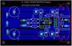
I like your design. Seems like you have lots of unused space left on that small board. If you stretch it out from left to right and move C1 and C2 to the left their might be room for regulators. I stretched it out using Paint to give you a visual.
Also, the way you connected the output-ground-plane to the main-ground-plane using two connection points might cause a ground loop, I'm not sure. Someone else might know better. I circled that on the pic.
Attachments
Gcollier
For cap's C5-6-7-8 and CD1-2-3-4 try to stick to n00ber's layout as that is the most ideal. (remember carlosfm's advice on this subject)
Regards
For cap's C5-6-7-8 and CD1-2-3-4 try to stick to n00ber's layout as that is the most ideal. (remember carlosfm's advice on this subject)
Regards
Hello guys,
I am very interested if we could come up with group buy. In the meantime I assembled small board for my own test since I have little experience with opamps. My question is - even do this buffer circuit is intended to be - buffer -what to change in order to get more gain? Would that be R4 or R3 on original design?
http://www.diyaudio.com/forums/attachment.php?s=&postid=197110&stamp=1056541528
Also, if C1 is eliminated, does value of R1 needs to be adjusted or it stay the same?
Thank you
AR2 said:Hello guys,
I am very interested if we could come up with group buy. In the meantime I assembled small board for my own test since I have little experience with opamps. My question is - even do this buffer circuit is intended to be - buffer -what to change in order to get more gain? Would that be R4 or R3 on original design?
http://www.diyaudio.com/forums/attachment.php?s=&postid=197110&stamp=1056541528
Also, if C1 is eliminated, does value of R1 needs to be adjusted or it stay the same?
Thank you
You could change either or both. I would change both.
How much gain do you want? You could get a gain of 6 by using 10K at R4 and 2K at R3. That would give you a gain of 6 which would be stable with most any opamp.
C1 is optional if you are absolutely sure you do not have DC on input.
R1 is also optional if you do not have much RF noise, but I would leave it and at the same value. You can have R1 without C1.
Cheers,
Russ
Thank you Russ,
Gain between 6 and 10 is perfect for me. I will test this circuit and compare it to another group buy that I am waiting to assemble X - Bosoz. Is there formula that I could use to calculate gain?
I tried this circuit without C1 and with R1 in place, and the sound was great, but with little roll-off on the top. I was afraid that by eliminating C1 and leaving R1 is lowering cut off frequency.
Thanks a lot for quick response.
No problem man. The formula to get gain is like this:
1+(R4/R3).
This is your basic non-inverting opamp gain formula. You will see it a lot.
I personally would not let R3 go below 1K. Both resistors should be good quality and the stereo pair matched. I use 1% metal film for those resistors. But you can really use anything you like, each type of resistor may have a slightly different sound.
I would say (with a good PS) this pre will compare quite favorably to just about anything.
Cheers,
Russ
Sorry I posted wrong circuit. Here is the correct one with opa6127 that I am testing.
http://www.pha.inecnet.cz/macura/buffer.gif
This is Pavel Macura's circuit.
http://www.pha.inecnet.cz/macura/buffer.gif
This is Pavel Macura's circuit.
My comments apply equally to that circuit.
I have used this (and others that I have built on protoboard with the same buffer/opamp) preamp with my gainclones, which are a couple of different stereo and dual monoblock LM3886s and LM3875s and with my stereo paralleled LM4780s.
This preamp would be a good source to any single ended input power amp I can think of.
I know that there are lots of DCX2496 users out there, that are wanting to mod, so just to share my experience with you guys.
I am trying this in order to replace output portion of the DCX which is really bad. On the output of DA converter I have Lundahl 1674 which is line transformer in combination 1=1 in order to cancel DC (it could be used as 1=2 as well). I tried just with transformer in line, and the sound is great but needs some extra gain. This little circuit opa 627 and buff634 could work well for that purpose. Only thing is: for 6 balanced channels it will need 12 of this circuits. As I mentioned before I will test it with X - Bososz as well.
Thank you guys, great tread
jaudio said:AR2
What kind of amp do you plan to use with your preamp
It is whole mess of amps that I am ether building or using. For the bottom portion, as you know, I am experimenting LM 4780 in bridged paralleled version. ( Didn't work on the amp yet to try your PS recommendation) I already have one Mosfet 200W amp that is currently driving my Lambda 12" bass. I also have N - Channel amp Zeta 320, (another diy tread)
For mid which is PHL 100dB sensitive speaker driver I gave Cary audio vacuum tube mono-blocks with 2A3 tubes.
Finally at the top for my ribbons I am using GC 3875 in bridged combination. I will be trying mini Aleph, or Aleph 30, as my first class A experience. I have to say that this little GCs are just awesome.
I started a lots of projects, and now I am little bit stuck with available time. Hoping that in July I could finish all this.
Yep, and if you go R4=4,7k and R3=1K, you have a nice headphoneamp😉 R12 is not needed for that application. The OPA624/BUF634 preamp is no match for a BosoZ, though! Not to my ears at least. Maybe a bit more analytical, but the BosoZ plays more MUSIC😉1+(R4/R3).
Steen😎
steenoe said:R12 is not needed for that application.
I wish I understood the purpose of R12. I have never used it.
This hole circuit is actually made as a "Cabledriver", for that purpose R12 is important. For a Preamp like this, it is not essential. The "Macura-circuit" wasn't even meant to be a preamp, after all. It just happened to be very well suited for that purpose also🙂 Maybe our 'PMA' would care to elaborate a bit on R12? Hope he sees this, otherwise I could try and hint him🙂I wish I understood the purpose of R12. I have never used it.
Steen.
- Status
- Not open for further replies.
- Home
- Amplifiers
- Chip Amps
- GC Preamp Suggestions