Group buy.
All of this is dependant on N00bers wishes, but if he wants me to I am willing to organize a group buy.
I would like to see n00bers next revision, as I believe it will be better for the general public. But based on what I have seen so far, this design is a great candidate for a group buy.
What do you think N00ber?
Good stuff 😀, i 'm glad everything worked out in the end, and I feel sorry about you loosing some 627's in the process, it would have been costly.
I allready have Russ' suggestions for improvements are there anymore?
I will however NOT be adding a pot onboard, as this is something which limits casing and location for the boardif this goes for a group buy.
When i set out to do this project, it was really for my
personal benefit, and hence the design criteria was based on that i.e. I was planning or replacing an opamp section in a preamp and decided to max it out rather than just replace the opamp.
It could also be used as a poweramp buffer, although a little overkill, and for that reason a pot is not needed.
It takes more effort not to use the onboard pot, than to solder one in with some wire, IMO, and I dont like pots on board either, so there 😛
Give me a couple of days, maybe to the end of the week(busy with work) to get some work done on the rerouting, and suggestions I will keep you all posted on the updates.
I have no problems on this going for a group buy, in fact I would be quite honourd
One thing i will definatley do is reduce the size of the input capacitor to the same size as the PSU bypass caps, not the same value just the phsycal dimensions, does anyone have any objections?
The size currently is way overkill, IMO.
Ok im off back to work now
n00beR
One thing i will definatley do is reduce the size of the input capacitor to the same size as the PSU bypass caps, not the same value just the phsycal dimensions, does anyone have any objections?
Sound like a great idea to me!

While I am not opposed to double sided boards, As things are I am not sure there is any benefit to going double sided. The boards is very simple, and that is a good thing. Also it will be cheaper single sided.
So I really like the idea of a single sided board.
So I really like the idea of a single sided board.
Do we realy need the input cap on the PCB? If one just uses a cap with leads (auricap, etc). I also don't mind that the pot is not integrated on the PCB, makes it much more versatile.
Great job so far n00beR. Also thanks to Russ for being the guinea pig😀
Great job so far n00beR. Also thanks to Russ for being the guinea pig😀
How about adding some mounting holes. I improvised 3 (all I could fit) on the ones I etched. They are so small the 2 on opposite corners would be enough.
Only other suggestion, since they are so small would be to have like 4 or 6 per board with scoring. Buy one board, get 6 channels. Or, maybe a couple of channels and a PS board, to make a complete package.
Only other suggestion, since they are so small would be to have like 4 or 6 per board with scoring. Buy one board, get 6 channels. Or, maybe a couple of channels and a PS board, to make a complete package.
BrianDonegan said:How about adding some mounting holes. I improvised 3 (all I could fit) on the ones I etched. They are so small the 2 on opposite corners would be enough.
Only other suggestion, since they are so small would be to have like 4 or 6 per board with scoring. Buy one board, get 6 channels. Or, maybe a couple of channels and a PS board, to make a complete package.
Yes, I like all of the above ideas. The mounting holes were very much appreciated Brian.
Russ White said:
Yes, I like all of the above ideas. The mounting holes were very much appreciated Brian.
Russ,
Glad to hear that the boards finally worked for you...I seem to recall suggesting replacing the opamp a few posts back...if memory serves. Troubleshooting is always such a headache, you try everything until the oh so obvious slams you in the face and solves your problem...been there for sure! 😀
Anyway, I'm glad to see this might finally go to a group buy, I won't need it since I etch my own boards, but it is nice to see nonetheless.
G.
Gcollier said:
Russ,
Glad to hear that the boards finally worked for you...I seem to recall suggesting replacing the opamp a few posts back...if memory serves. Troubleshooting is always such a headache, you try everything until the oh so obvious slams you in the face and solves your problem...been there for sure! 😀
Yeah, I had meant to switch the 627s for 227 right after you suggested it. (Actually I had even thought of it myself in some dark recess) But I was still not sure if there was some deeper issue with the PS. So I tried a few other things first. I have no tester for opamps, so I can only "sacrifice" good ones to test a circuit. I did not really feel like throwing opamps away until I did a few tests. Last night's revelation after putting the 277s in was largely in part to the suggestion from you and my own brain a while back.
In any case, I have had 627s, and many other single opamps in today with great success.
I have done quite a lot of testing today, and I am very happy with my setup.
Thanks G. Your suggestion helped me pull the trigger. 🙂
Prototype #2?
N00ber,
I am getting ready to order some boards for a seperate group buy which you can read about here:
Mauro's REF GC GB
I can add a few boards cheaply as I already have an order. If you have made good progress on the next revision of the 627/634 preamp board I would be happy to order some. 🙂
N00ber,
I am getting ready to order some boards for a seperate group buy which you can read about here:
Mauro's REF GC GB
I can add a few boards cheaply as I already have an order. If you have made good progress on the next revision of the 627/634 preamp board I would be happy to order some. 🙂
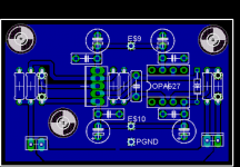
Ok here is what i have so far.
Things added:
*Mounting Holes
*BUF634 BW mode resistor or cap location
*Pads at input to allow option of cap instead of resistor
*Signal ground and power ground now connected
*Only one mounting pad for psu wires (+V, -V, and Pgnd), instead of connector blocks.
*More space to allow for easy mounting of BUF634 heatsink.
*Board components spaced out a little bit, due to board being slightly larger.
What do people think of the board now? better or worse, more room for improvement?
Please give me your suggestions.
Thats a good idea, is anyone working on a PSU for this or is there a good option allready available?
n00b
Things added:
*Mounting Holes
*BUF634 BW mode resistor or cap location
*Pads at input to allow option of cap instead of resistor
*Signal ground and power ground now connected
*Only one mounting pad for psu wires (+V, -V, and Pgnd), instead of connector blocks.
*More space to allow for easy mounting of BUF634 heatsink.
*Board components spaced out a little bit, due to board being slightly larger.
What do people think of the board now? better or worse, more room for improvement?
Please give me your suggestions.
Or, maybe a couple of channels and a PS board, to make a complete package.
Thats a good idea, is anyone working on a PSU for this or is there a good option allready available?
n00b
Attachments
Awesome!
Wow! Very nice noober, a couple of ideas if you don't mind:
1) flip the cap on the V+ side of the buffer to make mounting a heatsink easier.
2) Consider trying to get the mounting hole on the lower left more toward the lower left corner for the the same reason as number one. You could do this by slightly rerouting the SG plane from/to the buffer.
3) Instead of a direct connection between the two ground planes, make two pads. Then there are lots of options - leave it open, jumper it, use a low value resistor for isolation.
I like the power and ground changes.
Very good work!
I agree with Russ his comments. It will make a great board even better. Nice job sofar n00ber! (me want one for sure)
regards
regards
I think Russ's ideas are very good. In addition I'd prefer to get rid of the connectors an have bigger pads for the in/out wires.
looks quite good, cute too.
however, inputcaps this small is had to come by, at least i have trouble getting them small sized.
if possible, make it possible to use 22mm Rm caps like the one found here if you paste in "2447-7500PF".
hope you can find the place for it.
Id be in for a pair, if getting it combined with the mauro gc board is possible.
-Marius
demogorgon said:looks quite good, cute too.
however, inputcaps this small is had to come by, at least i have trouble getting them small sized.
if possible, make it possible to use 22mm Rm caps like the one found here if you paste in "2447-7500PF".
hope you can find the place for it.
Id be in for a pair, if getting it combined with the mauro gc board is possible.
-Marius
Hi there Marius,
I could not connect to the link you posted. However is this the device you are referring to.
It shouldn't be a problem to add it, but it will slightly increase the size again.
I dont want to drasticly change the layout from its current state. Once this one is finalised I may work on another version that has "little improvements", but that depends on how happy i am with tis one

This would allow this kind of addition with less of a size impact.
But thats for the future.
n00beR
EDIT:
On closer inspection if the cap you are looking at has the dimensions "20.07 x 7.87" this could probably be added with no change in size.
However it would hangover the -in resistor, the CRD and stick out a little over the edge.
If there is enough demand for it I will add it, otherwise the leads could be bent sufficiently to fit.
First of all the current design looks great, and I would be ready to purchase them as is. That being said, I do have a couple of comments.
Yes I realize these comments are too late for the current board design, but I thought I would suggest them anyway in case anyone else is designing a similar project with the 627 and 634.
I would like to see a version of the PCBs with adjustable regulators on the boards, as it is best to have them as close to the opamps as possible. Being adjustable, different power supply voltages could be used (by changing out resistors) based on what tranny voltage is used. This could be an easy way to use this pre inside a GC with its current power supply.
Using the opa627 and buf634 in these designs results in an expensive parts list and a high end product if designed right. Therefore I see using on-board regs as necessary if you are going this far already.
I like Dave's thinking, And I think his suggestion is a great idea for a larger board, especially a stereo board.
Let not forget however that while this board is for the 627/634 it will actually support just about any single opamp (ad8610, opa227/228, opa277, LT1115, etc..) So cost is actually quite arbitrary. You could also use any buffer with the same pinout of the 634.
Also, while this preamp sounds absolutely fabulous with a regulated PS (I am currently running it as such), it also sounds amazingly good even with a simple unregulated PS. I think that should be a builder's option.
Plus, there is something to be said for this board's simplicity/size. Still, I would love to see a board with Dave's ideas implemented.
- Status
- Not open for further replies.
- Home
- Amplifiers
- Chip Amps
- GC Preamp Suggestions