Gcollier said:
Hmm, not sure if you are experiencing some other issue, but it works fine for me.
1. Open the board file.
2. From Library on the main menu select OPEN, choose the library file
3. From Library in the editor window menu select Package
4. Select The package you need to modify.
5. Click the Display button (layers) and hide the tPlace layer
6. Select Change tool and Drill, click the elipsis and enter a size of 0.01
7. Click all the pads you need to change.
8. Click the change tool and select Diameter, choose your size then click all the pads to change.
9. Save the library file
10. Close the library editor
11. Click Library, Update all
That's it
Yep got it, cheers. It was the "change" button I missed.
tobias_svensk said:Max, so you understand what i said? 🙂
Yes, perfectly 😉
progress report
I have implemented N00bers boards.
The news is not so good, well at least not yet...
Last night I finally recieved the parts I needed to finish the stereo preamp.
I had previously tested one channel with direct wire from a partable CD player, it worked OK. But, I never really listen to things in mono for very long...
Now, with both channels in the case and both connected to the 10K stereo pot I get out of control oscillation and very hot chips.
I do not have the 22pf cap in series with the opamp out and opamp -in yet. I will try this later today when I get back from work. But right now it is unlistenable. 🙁
Some observations on the PCB design:
1) Maybe there should be optional pads for a resistor in series between the opamp out and the buffer in. I have found the the few preamps I have built previous to this one sound better with that resistor.
2) I think having two pads each fpr V+ and V- is overkill as they will almost always be fed by the same PS. I would just make one of each, or make the second pad optional (builder simply cut a trace and use 3 pin header instead of two).
3) The way the output resistors are laid out the only way to mount a heatsink for the buffer flush to the PCB is the mount the resitors on the bottom, and even then there is no good place to drill for the mounting screws. Maybe consider moving the output resitors? Not sure I know a good solution here. Possibly no heat sink is even desirable. Just a thought.
4) Why two power ground connectors? I wonder if this could be simplified to one. I think a single 3 pin header for V+/- and PG would make the wiring job much simpler, and this is such a small board that it gets really busy with wires.
5) I would consider adding pads for a small cap (10-100pf) from signal in to signal ground. This will help out those with a lot of RF (like me). For those who don't need it it could be omitted.
6) In my brief and very humble experience the buf634 sometimes does not work best with a straight wire between V- and the BW pin, it is usually better to add a resistor there (I have used between 200ohm and 1K). I wonder if the board could provide this option. Those who did not want it could jumper the pads.
Thats it. I sure hope I get it listenable soon.... until then at least I hope the feedback is constructive.
Thanks for everyting,
Russ
Hi Russ-
Don;t forget, as well, that I did a ground merge ground plane on the foil side. I hope I didn;t mess up the grounding when I did this, but it is something to review. I'll take a look tonight. Anyone else?

Don;t forget, as well, that I did a ground merge ground plane on the foil side. I hope I didn;t mess up the grounding when I did this, but it is something to review. I'll take a look tonight. Anyone else?
Thanks for the feed back Russ, I hope the output/feedback cap solves your problems for the moment.
As for the rest of your suggestions i will get on it asap.
As for the rest of your suggestions i will get on it asap.
Re: progress report
Russ,
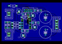
There are all very good suggestions. Unfortunately, with a nice symetrical board like noobers rerouting the power supply will get ugly, and yes I agree one connector is plenty. The picture that I have attached shows my own version of this preamp, I opted not to use the cap from in to out on the OPA as I don't find it helps much at a reasonable gain. If I need it it can be soldered directly to the pins under the board (it's a damn small cap). The output resistors on this board are out of the way so you can heatsink if necessary. The only thing that I ma not fond of is the supply routing in my design...but it works and I get no noise. It also gives a seperate signal and power ground if you look closely.
G.
Russ White said:I have implemented N00bers boards.
The news is not so good, well at least not yet...
Last night I finally recieved the parts I needed to finish the stereo preamp.
I had previously tested one channel with direct wire from a partable CD player, it worked OK. But, I never really listen to things in mono for very long...
Now, with both channels in the case and both connected to the 10K stereo pot I get out of control oscillation and very hot chips.
I do not have the 22pf cap in series with the opamp out and opamp -in yet. I will try this later today when I get back from work. But right now it is unlistenable. 🙁
Some observations on the PCB design:
1) Maybe there should be optional pads for a resistor in series between the opamp out and the buffer in. I have found the the few preamps I have built previous to this one sound better with that resistor.
2) I think having two pads each fpr V+ and V- is overkill as they will almost always be fed by the same PS. I would just make one of each, or make the second pad optional (builder simply cut a trace and use 3 pin header instead of two).
3) The way the output resistors are laid out the only way to mount a heatsink for the buffer flush to the PCB is the mount the resitors on the bottom, and even then there is no good place to drill for the mounting screws. Maybe consider moving the output resitors? Not sure I know a good solution here. Possibly no heat sink is even desirable. Just a thought.
4) Why two power ground connectors? I wonder if this could be simplified to one. I think a single 3 pin header for V+/- and PG would make the wiring job much simpler, and this is such a small board that it gets really busy with wires.
5) I would consider adding pads for a small cap (10-100pf) from signal in to signal ground. This will help out those with a lot of RF (like me). For those who don't need it it could be omitted.
6) In my brief and very humble experience the buf634 sometimes does not work best with a straight wire between V- and the BW pin, it is usually better to add a resistor there (I have used between 200ohm and 1K). I wonder if the board could provide this option. Those who did not want it could jumper the pads.
Thats it. I sure hope I get it listenable soon.... until then at least I hope the feedback is constructive.
Thanks for everyting,
Russ
Russ,
There are all very good suggestions. Unfortunately, with a nice symetrical board like noobers rerouting the power supply will get ugly, and yes I agree one connector is plenty. The picture that I have attached shows my own version of this preamp, I opted not to use the cap from in to out on the OPA as I don't find it helps much at a reasonable gain. If I need it it can be soldered directly to the pins under the board (it's a damn small cap). The output resistors on this board are out of the way so you can heatsink if necessary. The only thing that I ma not fond of is the supply routing in my design...but it works and I get no noise. It also gives a seperate signal and power ground if you look closely.
G.
Attachments
G.,
I like your layout.
I looks like the "outside/signal" groundplane and the "inside/power" are indeed seperate. This being the case, where do you join them? Can I seee a photo?
With N00bers boards I have, I ran a wire from the signal out to the power supply GND between the last filter cap.
Maybe I have have screwed up my ground? When I turn on the power(I only leave it on for second attached to very cheap headphones) I can hear a definite 60hz/120hz humm.
Also, would it be rude to request the brd file for that design? I may try etching it myself.
Thanks,
Russ
Russ White said:G.,
I like your layout.
I looks like the "outside/signal" groundplane and the "inside/power" are indeed seperate. This being the case, where do you join them? Can I seee a photo?
With N00bers boards I have, I ran a wire from the signal out to the power supply GND between the last filter cap.
Maybe I have have screwed up my ground? When I turn on the power(I only leave it on for second attached to very cheap headphones) I can hear a definite 60hz/120hz humm.
Also, would it be rude to request the brd file for that design? I may try etching it myself.
Thanks,
Russ
Russ,
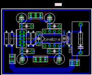
The power supply and signal grounds connect right at the PSU connector. I am actually going to modify this a bit more then I'll post the board fie (I'm more than happy to share).
G.
Ok, thats what confuses me, if the Sg and PG are joined on the PCB at the power connector, than are they really seperate?
Russ White said:Ok, thats what confuses me, if the Sg and PG are joined on the PCB at the power connector, than are they really seperate?
Russ,
The idea is to keep them seperate until they meet at the "star ground" or central ground point. This is usually the center of the PSU capacitors. In reality, no they are not physically seperate. Take a look at the .BRD file I attached. It has some very minor changes from what I posted earlier...I may have improved the grounding further. Basically this boad has three groundplanes that ar "star grounded". One for the PSU caps, one for the output ground, and one for the signal. The only place these meet is at the central ground connector that goes to the PSU, and this is located very close to the middle of the main PSU caps. The version I etched of this setup is a stereo one I posted much earlier in this thread with the DS1802 volume control. The grounding is nearly the same except that the output and input share a common groundplane. There is a finished photo of it somewhere in this thread. I plan on etching a couple of these units myself to see how they sound, and see if there is any improvement of the previous rendition. By the way you will notice that there is no large input cap on these boards, I am using a small cheap Vishay MKT 0.47uF cap on the input, and am very happy with it. I also added a place to attach a cap to ground to kill any RF...totally optional.
😀
Attachments
Thanks G.! 😀 Most helpful! 
I thought that was what was meant, but sometimes my mind is very literal, so when I read "seperate" I think "really seperate".
I thought that was what was meant, but sometimes my mind is very literal, so when I read "seperate" I think "really seperate".
terminal?
OK, I was wrong. It does not seem to be oscillation, instead, both boards seem to be fully screwed. I get nothing but humm on both. I have tested all traces for continuity and shorts to ground and other traces, but I have not found any problem yet. Could there be a more fundemental issue?😕
I am a little frustrated, becasue I cannot see anything wrong at all.
I eleminated the input pot, and took the input direct, still no luck.
The power supply is fine. I have tested it with other circuits. It is just a tad under +/- 18VDC.
I have tested the cicuit with the input shorted to ground, still get very strong humm, almost like I am getting DC to out, but I have not left it on long enough to find out.
I suspected a soldering problem, so I tested one channel at a time. The problem is consistant accross both boards. I inspected each solder joint with my 10X loupe and found no cold joints, and no shorts.
I am sorry I do not have better news.
Russ
http://www.diyaudio.com/forums/attachment.php?s=&postid=637661&stamp=1115554286
http://www.diyaudio.com/forums/attachment.php?s=&postid=643518&stamp=1116272644
Input and outputground are connected but not to powerground somewere? or is it connected togheter at the PSU?
http://www.diyaudio.com/forums/attachment.php?s=&postid=643518&stamp=1116272644
Input and outputground are connected but not to powerground somewere? or is it connected togheter at the PSU?
Re: terminal?
Hmmm....could be a nasty ground loop. I see this board has two power connectors = two ground connections. I haven't looked that closely at the groundplane, but if it is unbroken across the entire board you can try disconnecting one of the ground wires to see if it helps. Also as Tobias mentioned...the signal ground needs to connect to power ground somewhere, try to jumper it with a pice of wire held on with some tape. Something else crazy you might try is to connect a wire from earth ground to the groundplane with an alligator clip or something. Also...this might seem obvious, but are your caps in the right way?
Russ White said:OK, I was wrong. It does not seem to be oscillation, instead, both boards seem to be fully screwed. I get nothing but humm on both. I have tested all traces for continuity and shorts to ground and other traces, but I have not found any problem yet. Could there be a more fundemental issue?😕
I am a little frustrated, becasue I cannot see anything wrong at all.
I eleminated the input pot, and took the input direct, still no luck.
The power supply is fine. I have tested it with other circuits. It is just a tad under +/- 18VDC.
I have tested the cicuit with the input shorted to ground, still get very strong humm, almost like I am getting DC to out, but I have not left it on long enough to find out.
I suspected a soldering problem, so I tested one channel at a time. The problem is consistant accross both boards. I inspected each solder joint with my 10X loupe and found no cold joints, and no shorts.
I am sorry I do not have better news.
Russ
Hmmm....could be a nasty ground loop. I see this board has two power connectors = two ground connections. I haven't looked that closely at the groundplane, but if it is unbroken across the entire board you can try disconnecting one of the ground wires to see if it helps. Also as Tobias mentioned...the signal ground needs to connect to power ground somewhere, try to jumper it with a pice of wire held on with some tape. Something else crazy you might try is to connect a wire from earth ground to the groundplane with an alligator clip or something. Also...this might seem obvious, but are your caps in the right way?
Is it the one at page 43 you have made? (n00bers posted by GeWa)
Yes, It is constructed as follows:
feedback resistor = 10K
feeback to ground resistor = 2K
input resistor = 6.8 ohm
output resistor = 6.8 ohm
input impedance resistor = 120K.
decoupling caps = .1uf and 47uf.
RF shunt cap between opamp out and inverting input = 22uf ceramic.
no other components were used.
Power supply is a simple unregulated +/-18V with a 450ma 25.5VCT trafo.
Tobias:
Input and outputground are connected but not to powerground somewere? or is it connected togheter at the PSU?
Yes they are connected together at the PSU.
G.:
I haven't looked that closely at the groundplane, but if it is unbroken across the entire board you can try disconnecting one of the ground wires to see if it helps.
Yes, this was actually one of my first thoughts. I disconnected one on the ground connections and made a solder bridge from SG to PG just because I have nothing to lose. Still it has the same problem.
Also...this might seem obvious, but are your caps in the right way?
No worries, I have been known to miss the obvious. Yes the caps are in correctly.
Russ White said:
Yes, It is constructed as follows:
feedback resistor = 10K
feeback to ground resistor = 2K
input resistor = 6.8 ohm
output resistor = 6.8 ohm
input impedance resistor = 120K.
decoupling caps = .1uf and 47uf.
RF shunt cap between opamp out and inverting input = 22uf ceramic.
no other components were used.
Power supply is a simple unregulated +/-18V with a 450ma 25.5VCT trafo.
Tobias:
Yes they are connected together at the PSU.
G.:
Yes, this was actually one of my first thoughts. I disconnected one on the ground connections and made a solder bridge from SG to PG just because I have nothing to lose. Still it has the same problem.
No worries, I have been known to miss the obvious. Yes the caps are in correctly.
Try chaging your input resistor to 680 - 1000 ohms, also change the output resistor to something like 50 ohms.
Also at +/- 18V you are maxing out the supply limit on the OPA627, try to regulate it down a little or throw a few diodes in series on the rails to drop the voltage a bit. Also, I don't suppose you have tried to throw in another cheap opamp like an OPA134 or something to see if the chip is the problem?
I kept the output resistor value low on purpose as I will likely be driving headphones for a while as when the Zout is too high they sound like kraaap.
The input resistor value was an experiment, I will substitute with 1K. Still this should not cause this sort of problem. I have built this same circuit on protoboard with no input resistor at all. Stll, I think RF noise rejection is improved with the higher value, so I see no harm in increasing it.
When I switch this to actual pre-amp duties I will likely increase the output resistor to 50ohm just in case I have some stray capacitance in any cables I use.
I will swap the 627 for a 227 when I get home from work. I will also switch out the PS for my +/-12V regulated PS.
Thanks for your suggestions. 😀
Wait a minute...
What's this?

tobias_svensk said:http://www.diyaudio.com/forums/attachment.php?s=&postid=643518&stamp=1116272644
Input and outputground are connected but not to powerground somewere? or is it connected togheter at the PSU?
What's this?
Attachments
- Status
- Not open for further replies.
- Home
- Amplifiers
- Chip Amps
- GC Preamp Suggestions